
Henry Quach
Optical EngineerLens Design Principles in Underwater Photography
Introduction
David Attenborough's most recent book, A Life on Our Planet, makes the astute observation that television forever reshaped the public's perspective on biodiversity. By seeing intimate glimpses into animals' lives in-situ (and not in an artificial environment), viewers "began to care for the natural world as they became more aware of it."
That thought - that a particular technology could espouse empathy and possibly even policy - fascinated me to look into the parallel partnership between wildlife photography and the imaging technology that supports it. A quick, cursory search brought me to zoologist and photographer Mark Carwardine's Origins of Wildlife Photography article in BBC Wildlife, February 2012. In his article, Carwardine emphasizes that the popularization and mass-production of the 35 mm format was influential because rapid exposures and low weight allowed the imaging of otherwise uncapturable subjects ("fast, distinct, dangerous, or shy").
Along these lines, it is mentioned that the famous explorer Jacques-Yves Cousteau comimssioned his own underwater camera, whose first design and built prototype (née "Calypso") was among the first wet cameras (i.e. the objective lens touches water). The Calypso design was eventually bought by Nikon in 1963 and became the original ancestor of the legendary Nikonos underwater camera series. An amazingly comprehensive historical exposition and pictorial archive about the Calypso/Nikonos story can be found here on Pete's dedicated website about the subject.
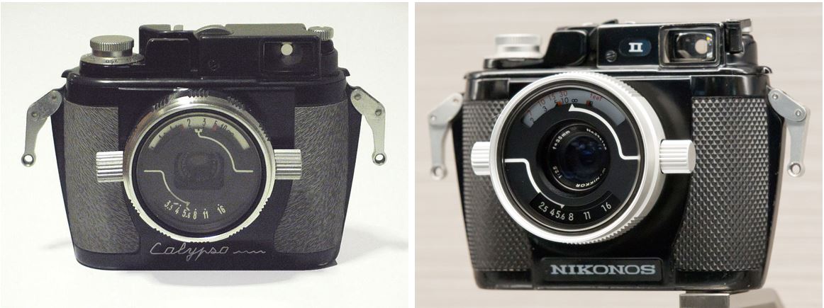
The original Calypso (left) was originally developed by La Spirotechnique with a f/3.3 28 mm lens. Picture by Jan von Erpecom, via Wikipedia commons. On the right is the second-generation Nikonos II with a f/2.5 35 mm lens. Picture by Morio, CC BY-SA 4.0.
Basic Underwater Lens Design Considerations
My primary fascination comes from both the optical and optomechanical challenges that a camera design must face in a hostile ocean environment. Explicitly laid out, they include:
Backscatter in Turbid Media
The ocean is inhomogeneous medium with invariably extant suspended media that scatter light. The nefarious small illuminants (whose particle size is much larger than the wavelength of visible light) include sand, plankton, and more and limit the distance by which distant objects can be resolved. It follows that subjects must be shot at a close distance and having a camera with a larger field of view is desirable. A consequence of taking photos identically to how one would on land would result in images with bright white circular artifacts across the field of view. Taking real, physically-shot panoramas of the coral cliffs from Finding Nemo would be enormously technically impressive.
Index
By virtue of changing the first media of immersion from air to water, the chief ray is already misguided through the rest of the system at first touch. Thus, we cannot simply transplant an air lens to water and expect it to maintain identical performance. Firstly, the refractive index will vary. Saline water is not simply a constant, but varies with saltwater concentration. Refractive index increases 0.00185 per 1% salt concentration, where this concentration is higher at the sea floor (solids accumulate here).[1] Not only that, the the saltwater concentration varies depending on the ocean - for example, the Atlantic ocean is known to have the highest salinity at 37 parts per thousand because evaporative processes are more dominant than the combined rainfall and water. [1]
Plane Parallel Plate: Field of FOV
You could put an entire air imaging system inside a mechanical housing with a flat plate "port" window, but this is what reveals the difficulty of desinging underwater lenses - that first interface. Understanding Snell's Law, \( n_a sin(\theta_a) = n_b sin(\theta_b) \), we must note that the first medium's index is not \(n_a=1\) as usual but \(n_w=1.34\), so the refractive power at the interface \(n_b=1.517\) is decreased. Following a chief ray backwards from the detector edge, the system, and then to the plane parallel plate, the AOI at the air-side of the PPP is much larger than entered (the AOI at the water side). Thus the subtense of the bounding chief ray at the edge of the field is smaller than it would have been in air.
Plane Parallel Plate: Distortion
At a flat image plane, the condition \(y' = ftan(\theta')\) defines perfect distortion-free mapping like that through a pinhole camera. Extending this perfect mapping to a refractive imaging system with a desired constant magnification, we have (with \(n=n_{w}\) and \( n'=n_{air} \)).
$$\begin{aligned} D &=\frac{y'}{y}\\ &= \frac{tan(\theta')}{tan(\theta)}\\ &= \frac{cos(\theta)}{cos(\theta')} \\ &= \frac{\sqrt{1-sin^2\theta}}{\sqrt{1-(n/n')^2sin^2\theta}}\\ &= \frac{\sqrt{1-sin^2\theta}}{\sqrt{1-n_w^2sin^2\theta}} \end{aligned}$$

This calculates the amount of distortion that is induced simply by having a plane parallel plate with asymmetric material interfaces. With \(n_w=1.340 \), the distortion gets as high as 10% at a 20 degree field angle, which is not sufficient for close-distance marine photography. Note that Laikin arrives at the reciprocal of this equation, but this still makes sense depending on how you define your distortion. Of course, the max angle of incidence in water will be \(\theta=48.27^\circ\).
Taking the AOI considerations of the last subsection, note that every single chief ray (some angular field object) from the underwater object will refract through the PPP and emerge at a different angle from another chief ray coming from the object. Either the optical system should have inherent negative distortion to compensate for this, or it will inherent this pincushion distortion from the asymmetric PPP interface at its own image plane. Important to note for later is that the wavefront aberration for distortion is given by an odd function of the pupil.
$$ W_{311} = (\overrightarrow{H}\cdot\overrightarrow{H})(\overrightarrow{H}\cdot\overrightarrow{\rho}) $$
Plane Parallel Plate: Lateral Chromatic Aberration
As we have been discussing the deviation of the chief ray, lateral chromatic aberration describes how the chief ray height varies with the wavelength. The dispersion of water is nontrivial, as it is seen to deviate from by \( \delta n = 0.0018\) from 400 to 650 nm. With higher AOI's, we see a smear of image point locations across the image plane because different wavelengths have experienced different magnifications. This perhaps clashes with or enhances whatever goal we have to preserve the chromatic fidelity of whatever light has made it to the depth we are imaging at (water selectively absorbs higher visible wavelengths such as red and orange). And another point, lateral color is also an odd function of \(\rho \). Both distortion and LCA can 'become' less of a problem if we decide to limit the field of view to ~ 20 degrees in water, though that's less of a solution and more like a design bandaid. Wakimoto's paper discusses the possibility of making the plane parallel plate an achromatic doublet,which corrects for LCA but unfortunately not distortion because residual power still exists at the interfaces. [2]
$$ \delta_{\lambda} W_{111} = (\overrightarrow{H}\cdot\overrightarrow{\rho})_{\lambda} $$
Design Paradigms and Solutions
Dry Lenses with a Hemispherical Dome Port
The reason why having odd functions of the pupil are important is because odd aberrations can be cancelled; deviations depending on the chief ray can have opposite signs and compensate for each other. Usually we know this in lens design as lens group symmetry about the stop, but the premise can be analogously applied elsewhere.
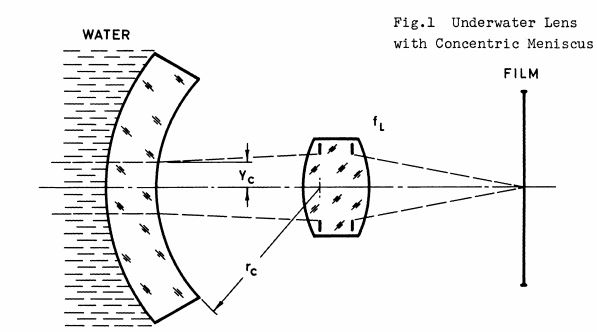
A popular solution that initially fully avoids the full redesign of a dry lens into a wet lens is that of a concentric dome. If instead of a flat port, a spherical port is set concentric to the entrance pupil location, then the chief ray behavior is automatically more tenable. If the center of a thin refractive dome is set concentric to the entrance pupil location along the imaging system's optical axis, chief rays from the underwater object do not refract as they pass through to the entrance pupil center along the optical axis. This is because the chief rays arrive normal through the hemispherical dome surface and straight to the entrance pupil center. As a result, the FOV in water and FOV in air are now identical and the excess distortion previously introduced by the plane parallel plate has vanished. Mandler adds to this and illustrates how this meniscus actually acts like a negative lens - it creates a virtual image of its own.
It is desirable for this negative lens to be as weak as possible, or with a large radius of curvature on both surfaces. Thus optimization is in direct contention with pressure requirements of any lens system of course. Domes will end up using acrylic rather than glass for the dome because the acrylic is cheaper to form and has a larger shear modulus than glass while having approximately the same index. As both are relatively brittle, we expect it to fail in shear than normal stresses.
I actually had trouble understanding this at first because the concentric dome has concentric surfaces and shouldn't this just act like a thin plate with no extra complications? Yet, because the material interfaces of the dome are different (seawater to glass, glass to air), the dome is a meniscus with negative power. Punching this into Zemax with a ROC of 50 mm, an entrance pupil diameter of 50 mm, a shell thickness of 5 mm, index of \(n_{nbk7}=1.517 \), and \(n_{w}=1.3333,\) for more intuitive calculation results, we get the following system layout, labeled with its cardinal planes.
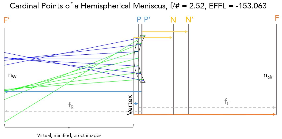
A camera residing inside the dry space behind the hemispherical acrylic meniscus must focus before F' in order to capture the virtual image. You can see John Greivenkamp's Field Guide to Geometrical Optics' page 12 to see how real objects are only produced as images at F' and closer.[3]
For a thin shell, the paraxial focal length of the system is \(f= -3R\). Since a dry optical system's entrance pupil is located at a distance \(R\) from the hemisphere, we require that the system must be able focus from the rear focal plane (F') up to the vertex of the hemisphere in reduced thickness space, or a distance of 4R in air space. This way, the minified virtual image can be relayed into the actual optical system. Some unfortunate consequences of this creation is that Sidney Ray's Chapter in Applied Photographic Optics cites that Cousteau originally grounded the domes at their apex per the requirement of individual lenses - perhaps the accidental creation of a high order even asphere.[4] Some aberrations this system itself faces is that the image surface is strongly curved - in fact it is a sphere with radius of \(4R\). There is loss of detail, then, because the field curvature is so high and the focus of the lens is not at the film plane. Afocal correctors such as Ivanoff's exist (USPTO #2,730,014), which correct and relay the virtual image of the concentric dome to the dry lens, but I think they were very expensive. [5]
Dome ports are actually popular today for photography requiring half-water, half-air shots (that's how they do it!) and you can quickly query 'dome port lens' into the Amazon search bar to get one for your GoPro for ~$50.
Fun fact: the same negative meniscus effect happens outside of underwater imaging in training astronauts. Astronauts conduct zero-gravity mission training at the Neutral Buoyancy Laboratory in Clear Lake by suiting up and using exact replica of the ISS submerged in an olympic-sized indoor pool.[6] Space suit helmets are spherical (or elliptical) domes that would not have a significant refractive influence in space, but would do so if it were water and not vacuum outside their visors. Porter et al. found that am additional pair of glasses with a power of 2.356 diopters was well-suited to correct this effect across a survey of astronauts in training.
Wet Amphibious Lens
Now the main topic of discussion is lenses that are made to touch the water! Lenses that touch water have a front element also shaped like a dome because of desirable mechanical properties. Piecing together the technical information from Nikon's retrospective series on their lenses The Thousand and One Nights and Zenji Wakimoto's paper, we learn a few things: 1. The W Nikkor 35 mm f/2.5 (1963) is interchangeable with all descended Nikkonos camera bodies today 2. its architecture consists of a protective parallel plate as the first element and then a Double Gauss behind it 3. field curvature is not fully corrected but astigmatism performance is still good, of course when the field is stopped down. [7] It is incredible that an amphibious lens could exist and Koichi Ohshita provides photos of performance of that exact lens' on land in that Nikon vignette. [8]
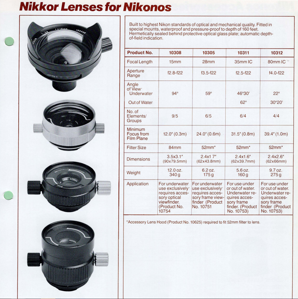
From Pacific Rim Camera, I found a quick catalogue for the Nikonos III main instrument and accessories offerings. The available lens encompasses amphibious and pure underwater types. The 15mm f/2.8 is bonkers with 9 elements and a FOV of 94 degrees in water. The lens hood reduces stray light, which we know is rampant in the ocean.
The Modern Nikonos Lens (SLR)
As for the lens for the most recent Nikonos - the Nikonos RS (1992) - it is for an SLR. The closest I could get to Nikonos's exact design was by looking at Laikin's reverse-engineering from Koichi Oshita's patent 'Photo-Taking Lens for an Underwater Camera' (USPTO #4,856,880, on behalf of Nikon). This is a 5 element lens consisting of a thick meniscus (positive shape factor) with negative power (for the same mechanical reasons as previously described). Together, they act as a reverse telephoto system, where the back focal length is much greater than the effective focal length, making room for the camera body's prism. Koichi's memoir includes the detail that multi-layer coatings finally made its way to the design - eliminating even "ghost images and flares in strong summer sunshine."
Interestingly none of these are cemented doublets but rather airspaced. Airspaced doublets bestow the advantages of higher speed because the separation of interfaces itself is a degree of freedom. I suspect that this was also an optomechanical consideration because the coefficient of thermal expansion is on the order of \(\alpha_{glass} \approx 5E-6[K^{-1}]\), which that of a cement is \(\alpha_{generic} \approx 63E-6 [K^{-1}]\). [9] The third and fourth elements, an airspaced crown and its flint, are made of N-LAF21 and SF4 respectively - in a configuration that very much resembles a reversed Gaussian doublet. This is opposed to the canonical Fraunhofer doublet where one wraps around the other, like in Klimt's "The Kiss".
The film plate cover is sealed with a gasket and swings out from the camera body rear, while the lens interfaces with the front camera body with an O-Ring. The Youtube Channel Fix Old Cameras had a thorough tutorial on how to clean a Nikonos camera body, revealing the construction. Some thing quite interesting is that O-Ring flange design is already a careful and delicate process. Balancing proper lens spacing and O-Ring cross-section width so the lens barrel is sealed to the body while maintaining blur-free imaging to the film plane must have been nightmarishly stressful (that or the depth of focus was designed to be generous). The Nikonos Project, a community that embraces the Nikonos camera, claims that there are in fact 18 O-Rings in the Nikonos V.
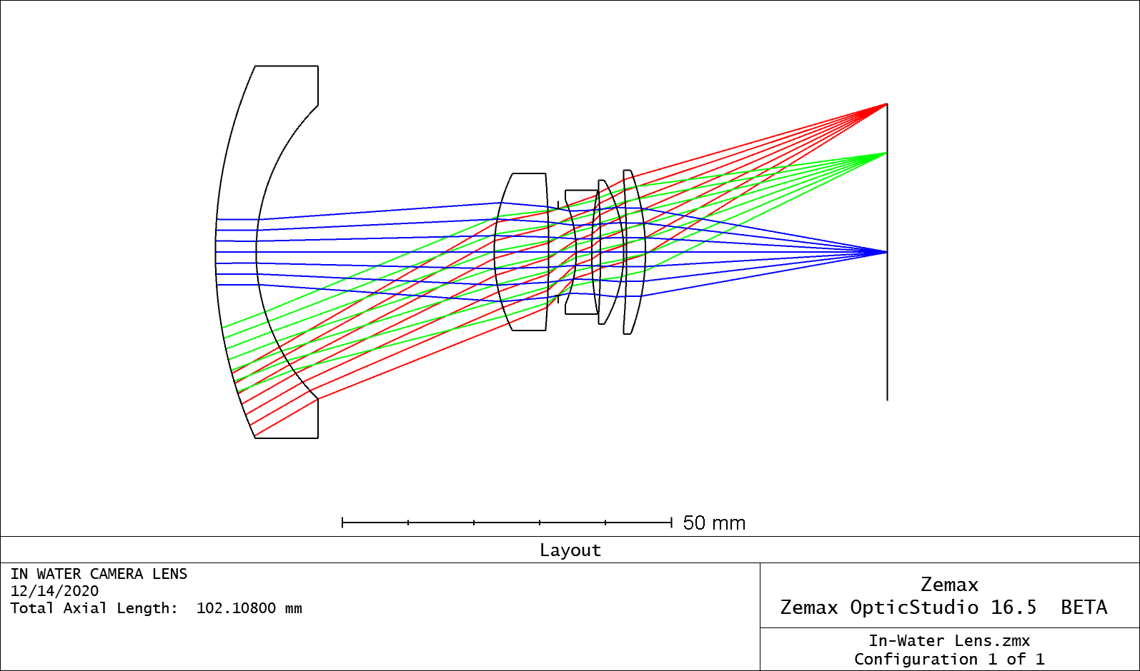
The elements, from left to right, include a weakly positive biconvex lens, a strongly negative biconcave lens, a positive meniscus (negative shape factor), and a weaker biconvex lens with sharper curvature towards the image plane. This was ported from Zemax's patent library from Laikin's Book. [1] Kudos to Laikin for having such a huge contribution to designs all around the world (many designs start from existing templates) - most textbooks do not give optical prescriptions, but his does.
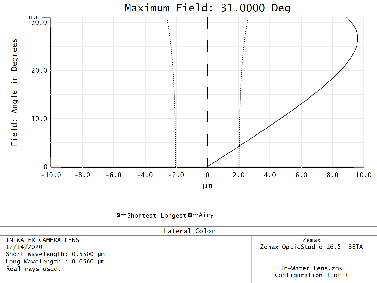
The lateral color increases with field all the way up to ~30 degrees. This means that the different colored spots will be smeared (or displaced) by up to 8.86 microns at the very edge of the field. Lateral color is the variation of magnification with color and the fact that the transverse displacement curve (black) reverses direction is highly indicative of the compensatory interaction between the flint and crown elements.
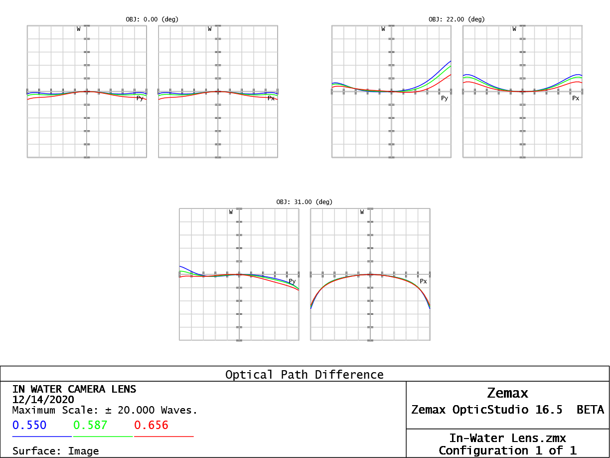
The OPD plot over several field angles is shown. From 0-22 degreees, the OPD is kept within a few (less than ~5 waves), while it increases up to ~20 waves at the full field. Excess coma is noticeable in the 22 degree and 31 degree fields in the tangential plots, while astigmatism evolves noticeable towarsd higher field angles. It is interesting that the field at 31 degrees maintains high lateral color fidelity.
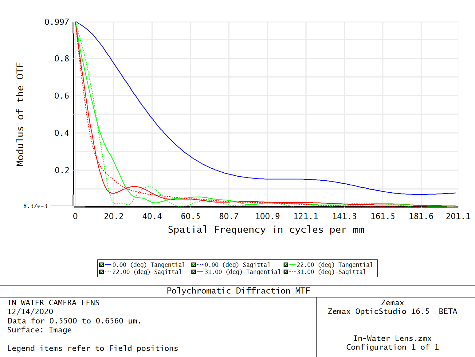
The MTF plot shows that we spatial frequency performance sharply drops after just 30 lines/mm. According to today's modern MTF guidelines, we want 50% contrast at 30 lp/mm and 30% contrast at 50 lp/mm. This was primarily developed as a criteria because of a photographic film's natural grain size. One of Rick Juergen's recommendations is that we have 50% contrast at 50 lp/mm. We have 0.62 contrast at \(\xi=30 lp/mm\) and 0.36 contrast at \(\xi=50 lp/mm\), which is pretty close. Given that the RMS spot size of the three fields goes from 16 to 30 to 83 mm, we can easily say the spot is limited by geometrical aberration and is hardly limited by diffraction.
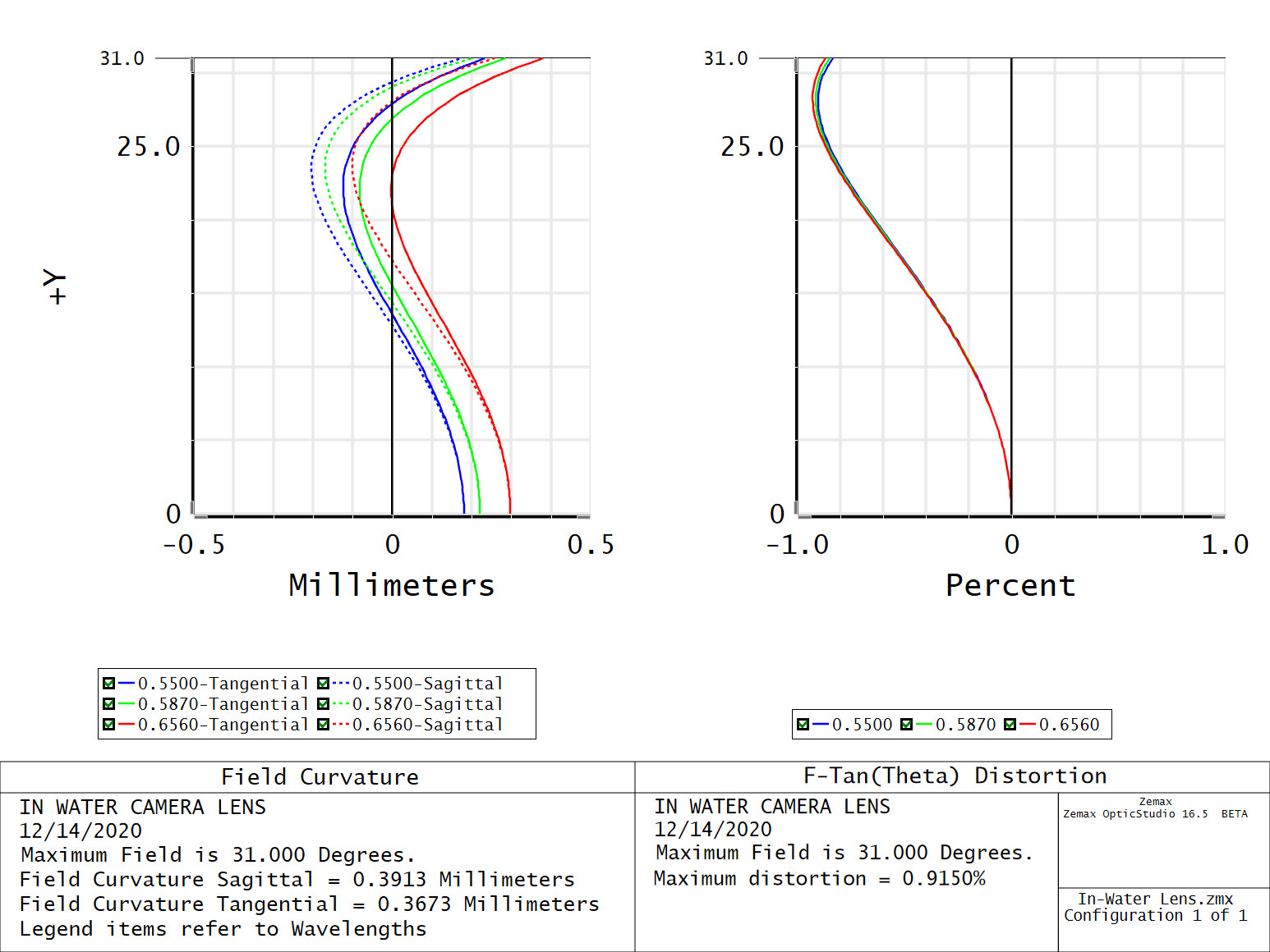
Finally, we observe field curvature lives within a 0.5 mm window, of course optimized for the 587 nm green line. Distortion, though moustache-like, is held to within 1 percent across the field for all colors which is amazing compared to the dry-lens-in-housing designs. The variation in magnification with chief ray height is noticeably resolved.
Conclusions
Because asymmetric seawater to glass and glass to air interfaces introduce a littany of aberrations, it is advantageous to design for object immersion from the start. These aberrations are primarily distortion and lateral color and skew our visible perception of underwater wildlife. There are new players for underwater photography in the market today - such as Canon's offerings of a ruggedized digital camera with an electronic detector rather than film. Despite this, the culture of underwater photography holds a high place the Nikonos. It has allowed the public, into and beyond the 1960's, to accrue enthusiasm for the undiscovered weirdness of life under the sea without the weirdness of optical aberrations. Thanks, David Attenborough, for a wild two-day venture into this niche lens design subfield.
References
[1] Laikin, M. "Lens Design: In-Water Lenses," Proquest Ebook, Taylor and Francis, 2006.
[2] McNeil, G. "Metrical Fundamentals of Underwater Lens Systems,” SPIE Optical Engineering, Vol 16 No. 2, 1977
[3] Greivenkamp, J. "Field Guide to Geometrical Optics" SPIE Press, 2004.
[4] Ray, S.F. "Applied Photographic Optics: Underwater Lenses," Focal Press, 2nd ed, 1995.
[5] Ivanoff, A. "Correcting Lens for Underwater Use," J. Soc. Motion Picture and Television Enngineers, Vol 69, 1960.
[6] Porter J, Gibson CR, Strauss S. Determining spherical lens correction for astronaut training underwater. Optom Vis Sci. 2011
[7] Wakimoto, Z. “On Designing Underwater Camera Lenses,” Photogrammetric Engineering, Vol 23. 1967.
[8] Ohshita, K. "Nikkor - The Thousand and One Nights No.8," Nikon Imaging Website.
[9] Yoder, P. "Mounting Optics in Optical Instruments," SPIE Press, 2nd ed, 2008.