Henry Quach
Optical EngineerA Study on 3D Printed Steographic Projections
Background
3D printed projections are nothing new to the maker community. A small light source (usually a bare LED) is placed above a thin spherical shell. Cutouts are designed to allow some light from the LED to pass through, which results in the apparent projection of some binary pattern onto a flat surface. The following projection was created by Henry Segerman, a mathematician who makes a lot of cool art and has published this work in his own book.
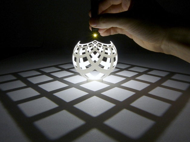
The original stereo projection published by henryseg on Dec 13, 2013.
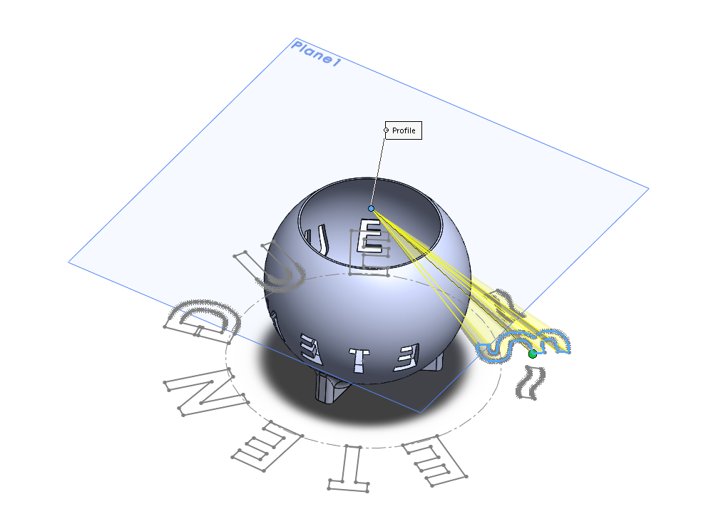
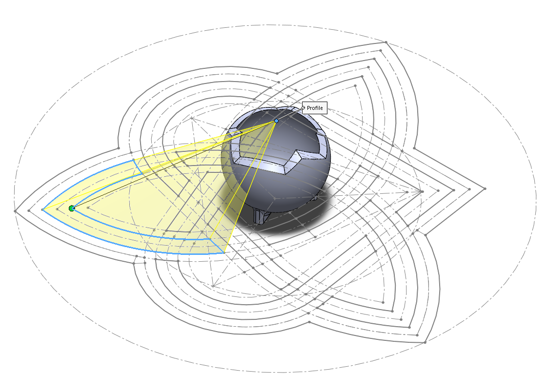
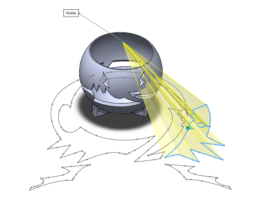
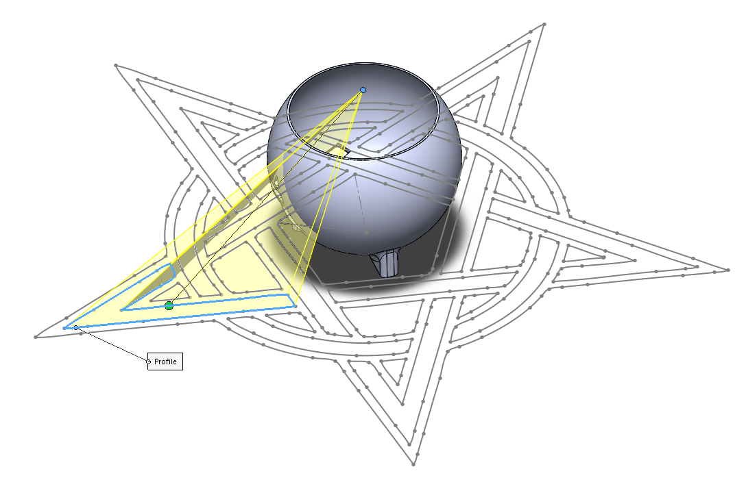
The design is implemented by lofting a closed sketch on a plane below the shell to a singular point at the apex of the sphere. For example, nimaid created a beautiful parametric model of a Celtic Knot Projection in SolidWorks. I examined her instructions and downloaded her native .sldprt file to learn about the creation process. What's nice is that lofting a flat closed vector in a plane often ends up with no self-intersection errors.
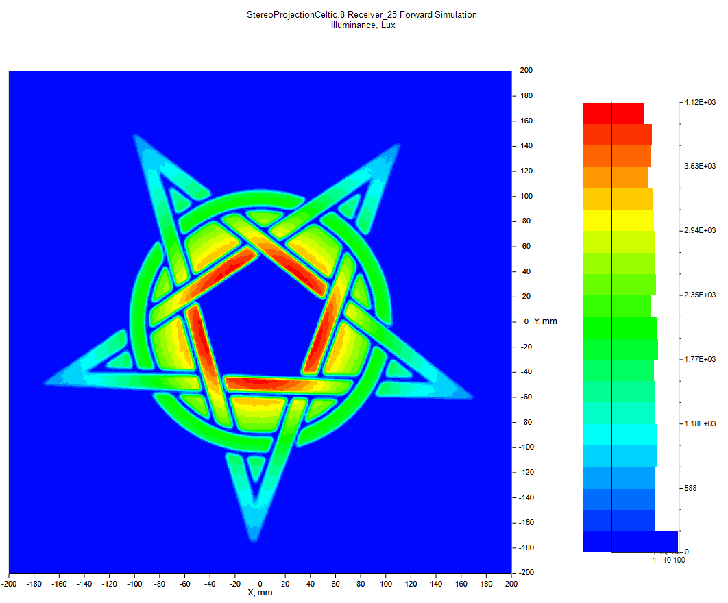
The principal assumption behind this design is that the small LED acts as a point source, radiating power in all directions with equal flux per unit solid angle. Since only the 'open' areas of the cutout allow light to pass through, the exiting light can directly strike the designated projection plane to form a pattern. Implicitly, the 'closed' areas of the spherical shell are assumed fully absorptive with no probability for 'second chance' reflections, like that of an integrating sphere. With these design principles, you can get very reasonable projection patterns, so long as your light source is small and placed close to the apex of the sphere. Simulating a point source at this position in LightTools with 5 million rays, this is the irradiance at a detector plane tangent to the bottom of the sphere. The projected pattern is pretty clear for the point source over a detector of 501 x 501 pixels (771k rays land on the detector; only 12.13% error at the least irradiated pixel).
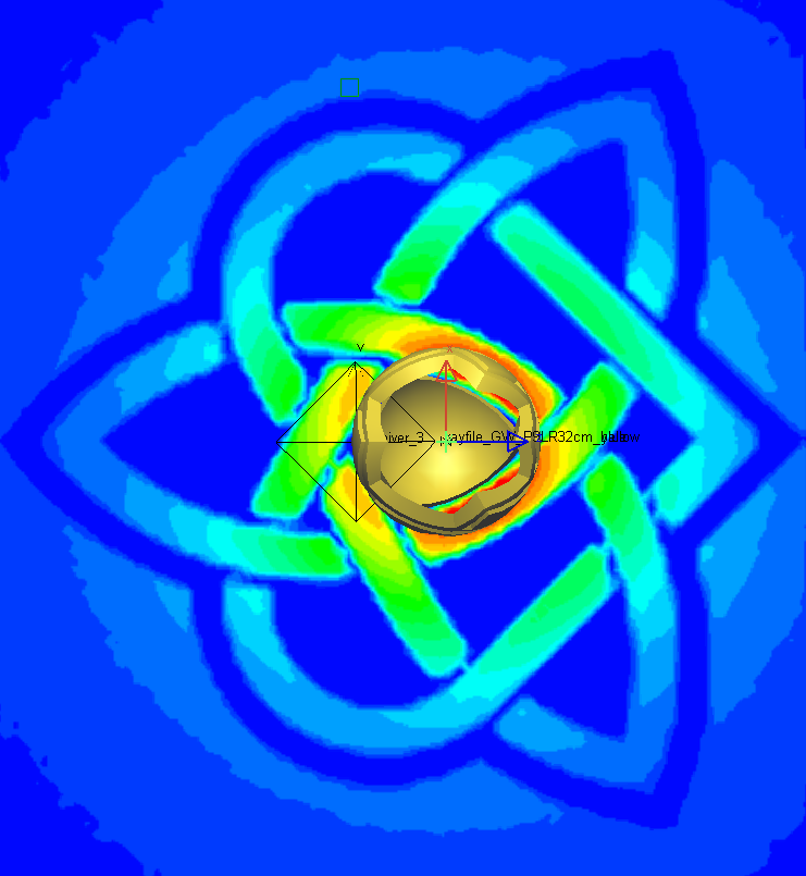
IDEAL CASE. Source: isotropic point at sphere apex; Material: 100% absorptive material; shell walls 10 mm thick; Detector: 501 x 501 px. Note that walls are set to 1 cm for easier printing and fewer mandatory supports.
Reconcilation of Illumination Assumptions with Reality
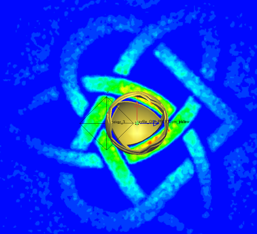
However, we don't see this performance in real life because our assumptions were not well-founded. The main detractor is that scale of an LED is too large to emulate a point source for the absorptive sphere. The effect is that is that edge contrast at the periphery of the projection is lower than what is predicted by LightTools. Here is what the extreme case of illumination might look like with a real light source.
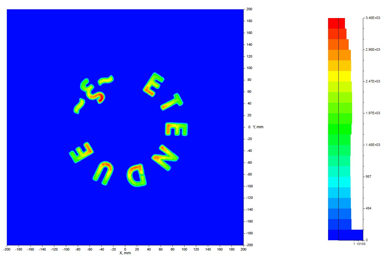
I chose a typical 5050 LED with a 4.6 mm diameter light with 120 degree FOV to represent the source. I obtained and traced the measured ray files for the OSRAM DURIS S8 (GW P9LR32CM LED). Since the ray files only contain 200K rays, undersampling is all but guaranteed for the detector size we'd like to use), so I traced the given rays with a 201 x 201 detector for a more modest ~22.7% error at the least irradiated pixel. The profile below actually resembles what the projection looks more similar to in real life, unlike the point source case.
Material Absorptivity
I originally that that maybe the non-zero reflectivity of the black filament played a role, but it really doesn't. Initially I guessed 95-98% absorption was reasonable, but man it's more like 99.9%. Plastic colorant manufacturers are eager to advertise their colors with great sophistication and even spectral specificity, but pretty none disclosed actual chemical compositions. Naturally, trade secrecy is a thing, but at least for black colorants, we can guess that Carbon Black is commonly used. Carbon Black is cheap, non-toxic, and easily absorbs the visible spectrum to 99.9%+ in PC. (Thank you Laser Welding of Plastics, 1st Ed.) Assuming that a competitive alternative would have similar performance, I just assumed 100% absorptance in the visible so that my raytraces would go faster. Ray tracing for even 98% reflectivity, the contrast at the edges was hardly affected. In pretty much all non-sequential raytracers, you can set your rays to terminate at some percent of output power, but even at 1000 allowed bounces the compounded effect was negligible.
LED Form Factors
Just for thoroughness, I chose the 5050's because they're so standard. The famous neopixel LED strips sold by Adafruit are very recognizable examples of 5050's, which indicate the form factor or packaging size. 5050's and 3528's are simply a 4 digit code that indicate that the dimensions of the light source is 5.0 mm x 5.0 mm or 3.5 mm x 2.8 mm. The actual light source is still identified by a SMD (surface-mounted) chip, such as a WS2812, SK6812, or SK9822. In this case, 4 separate tiny LEDs fit onto the 5050 form, while one is used for the 3528. (The 3528 is more suitable for single color applications.) Not that it matters in this case, but power supplies will matter for electronic lifetime considerations.
Also, in another digression, I'm used to enclosed style AC-to-DC power supplies, which are often seen in 3D printers. I like them because they are affordable, have flexible screw-in terminal connections and high maximum current output. Plug-in style AC-to-DC power supplies, are much more compact and actually fully enclosed, but have lower maximum current ouput. They are more environmentally resistant, but usually have a barrel jack connection, which may convenient depending on what you have on hand. I chose to proceed with with the first because they have better current capacity and more upgradable if I need to put multiple strips in parallel to stave off voltage dropoff over longer strip distances. The preference for low-loss power transmission is high voltage and low current. We know that transmission loss via joule heating is described by \(P_{Loss} = I^2R\).
However, by Ohm's Law, \(V = IR\), isn't power loss also described by \(P_{Loss}=V^2/R\) ? In the physics perspective, voltage describes the potential energy difference between two points per unit of charge. The work done by a unit charge from moving between these points is measured in Volts can be held constant by a constant voltage power supply. The flow of electrons through an object is current flow and is limited by the material's inherent resistance, measured in Ohms. However, Joule Heating is related to the voltage drop along the length of a wire, rather than the total potential difference between the two points. tl;dr go buy as high voltage LEDs because they'll last longer and are less likely to burn your house down with less current running through them. 24V's are what I'm going to use when I eventually make these lamps
Fun Designs
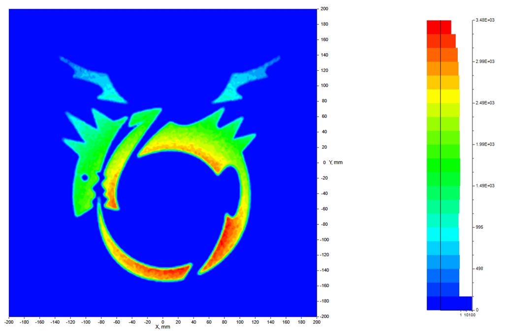
This is the Ouroboros, or the mark of the Homunculus from FullMetal Alchemist! It was a very smooth loft between all parts of the dragon. Note the significant nonuniformity between the upper and lower portions because the wing offsets the visual centroid of the pattern.
Just other fun patterns...
This is simply Etendue, which is... the fundamental consideration of illumination design.