
Henry Quach
Optical EngineerA Clocking Mount for Horizontally-Mounted Inflatable Optics
Project Background
The ability of space telescopes to gaze into our universe is critically dependent on aperture size. While large monolithic mirrors cannot be brought to space, deployable membrane reflectors are an interesting possibility. For example, the OASIS (Orbiting Astronomical Satellite for Investigating Stellar Systems) proposes using a 20-meter class inflatable reflector, operating at \(\lambda = 540 \ \mu m.\)
Without continuous access to laser trackers, I am interested in applying the N-Rotations technique, which measures the same optic at different clocked positions to remove the low order asymmetric shape error. For the measurement of an existing 1-meter diameter OASIS primary mockup, I would need to design a mount that enables mirror clocking, but introduces no more than \( \lambda/8\ =\ 67.5\ \mu m \) RMS surface shape into a stationary deflectometer’s surface measurement.
This is an unusual testing scenario because it strictly assumes that any deviation from perfect undeflected mounting counts as error. An experienced metrologist would account for the final deflected positions of the hardware each time it is remounted and therefore introduce far less than \( \lambda/8\ =\ 67.5\ \mu m \) RMS error. The design problem statement presumes a situation where a non-expert operator is repeatedly measuring the mirror and must re-fixture without the opportunity to recalibrate hardware. I chose to take on this project for Optomechanical Design and Analysis as well as poke around this possibility for research.
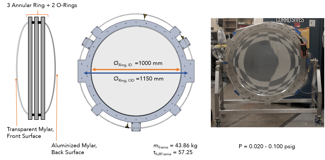
Figure 1. An inflatable membrane mirror is constructed by clamping two mylar sheets between three machined aluminum rings with O-ring interfaces. During inflation, the rear aluminized mylar becomes the true concave reflecting surface of interest, while the clear convex mylar front surface helps hold pressure.
A 1-m membrane reflector was built in 2019 and is the UUT for this project. Shown in Figure 1, the rear aluminized reflector naturally forms an oblate ellipsoid. It is desired to prototype annealing processes to alter the membrane’s shape, which implies iterative remounting of the assembly and whose vertex sag can inflate up to 70 mm. Within the clamped aluminum rings, internal O-ring glands have an outer diameter of 1066 mm and it is undesirable for any mounting (say, from a bolt) effects to introduce stress into the sealing interface periphery.
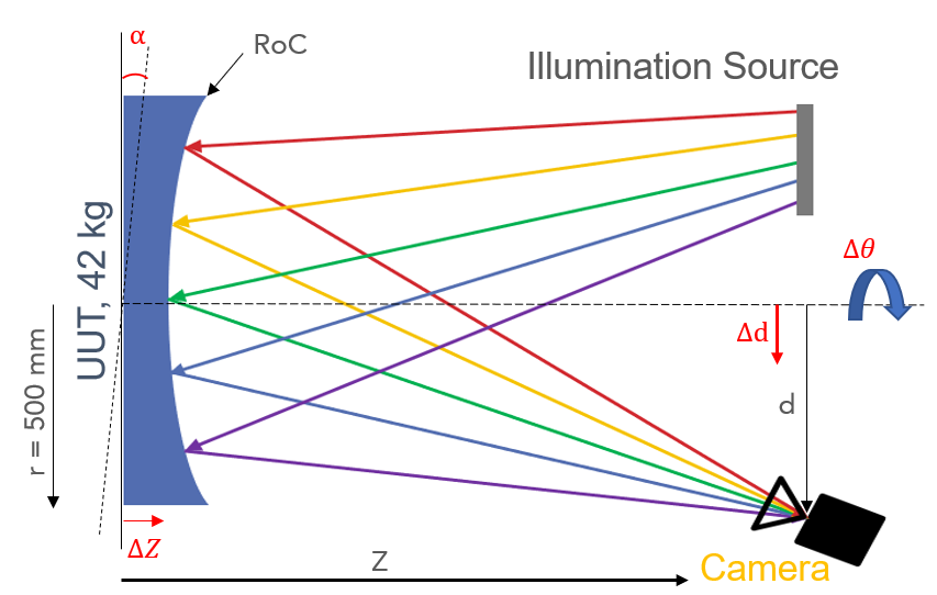
Figure 2. In this figure, the UUT has no tilt \((\alpha=0\ deg)\), despace \((\mathrm{\Delta z}\ =\ 0\ mm)\), decenter \((\mathrm{\Delta d}\ =\ 0\ mm)\), or clocking \((\mathrm{\Delta\theta}\ =\ 0\ mm)\). R is the medial radius of curvature, Z is the optic measurement distance, d is the nominal distance between UUT axis and the camera aperture stop.
In this project, three requirements are explicitly defined (summed up in the following table too):
Performance will be based off the \(\lambda/8\) RMS requirement, defined in terms of the Noll Zernike set. Since power and astigmatism are the dominant features of the membrane optic, these three components will add in quadrature to calculate the final surface RMS.
Survival will be based on the lack of stress failures for a FOS > 3 where in addition to gravity, a temperature load of ±30K will also be applied and checked.
Form Factor is perhaps an extension of the survival requirement, but the mount must accommodate the full sag of a nearly bursting optic with sag = 80 mm. Because the O-Ring interface has been preloaded in order to seal gas, induced mounting stress cannot seep into this gland’s outer diameter. This will be defined as the distance where the peak stress from the mounting connection reaches 5% of its value. The outer gland radius (542.5 mm), which is 10 mm away from the edge of the extruding rectangular tab. The width of the rectangular tab is 70 mm, so if the induced stress distribution fades off within a radius of 40 mm, the design is in the clear.
| Metric Type | Specification | Comments |
| Performance | \( \lambda/8 \le\ 67.5\ \mu m RMS \) | \( \varepsilon_{tot,\ rms}=\sqrt{Z_{rms}^4+Z_{rms}^5+Z_{rms}^6} \) |
| Survival Conditions | \( FOS > 3,\Delta T = \pm 30K \) at 8 symmetric positions about axis | Von Mises Yield Criterion, (assumes all metal parts in my mounting assembly) |
| Form | Max Sag > 80 mm 10 mm distance from <5% Excess Stress at O-ring Gland | Mounting stress due to bolts should not bleed into periphery of sealing connection. |
The top level error budget with major categories is broken down in Figure 3.
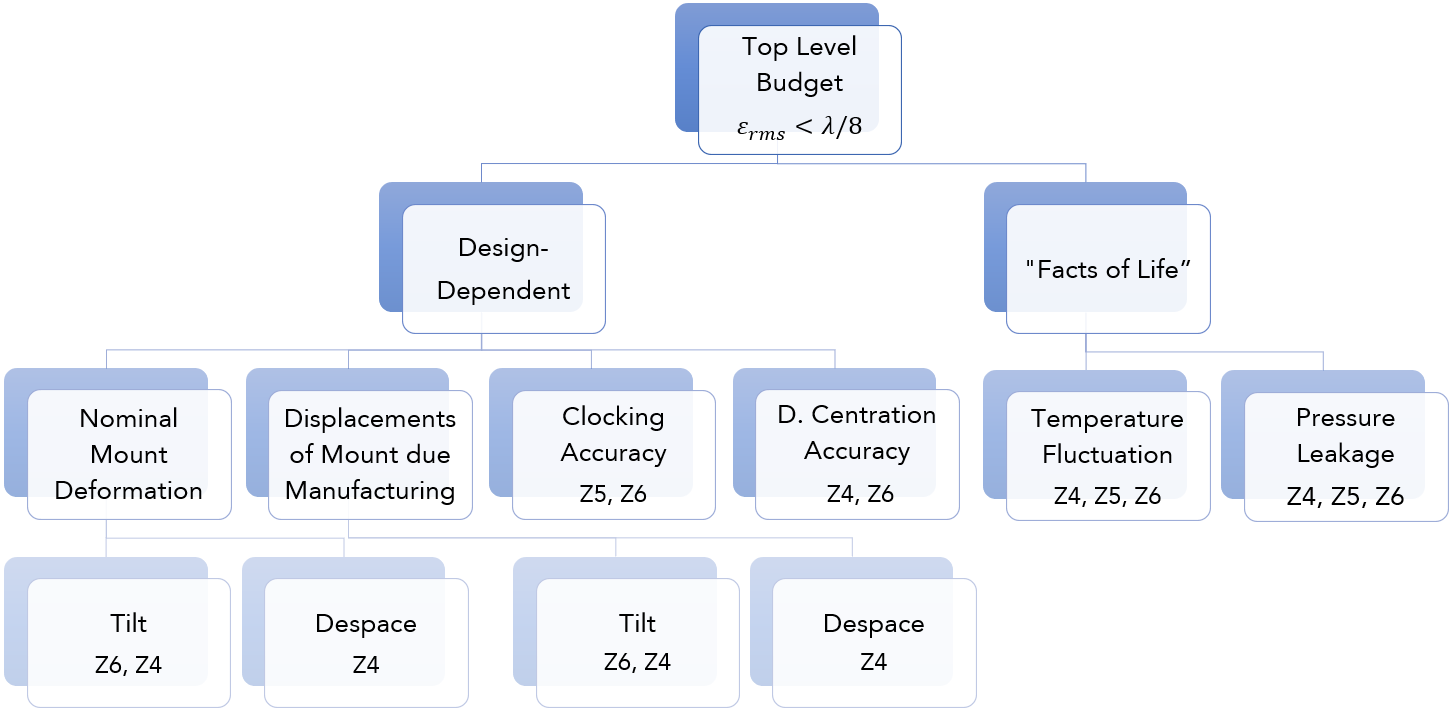
Figure 3. Error Budget Breakdown. Observe that some 'facts of life' are things that belong to the environment or inherently to the testing scenario. These terms are baked into the final tolerance budget (and we'd be screwed if they exceeded the \( \lambda /8 \) requirement already!), so we have to focus on the design-dependent decisions to meet the allocation.
First Order Calculations, Considerations, and Design Form
Rotating Deflectometer vs. Rotating Mount
I originally wanted to rotate an on-axis beamsplitter deflectometer, but that design path was eliminated after PDR because its error budget far exceeded the allocated budget. While the preliminary design only included one extra beamsplitter, the number of additional interactions significantly complicated the system. When only considering pointing, any tilt of the optic was sensitive to \(11 \mu m/ \mu rad \) which was exceptionally high. This is on the order of angular runout for ABEC-7 to ABEC-9 bearings. Reflecting on this, I altered my path to simply rotate the UUT.
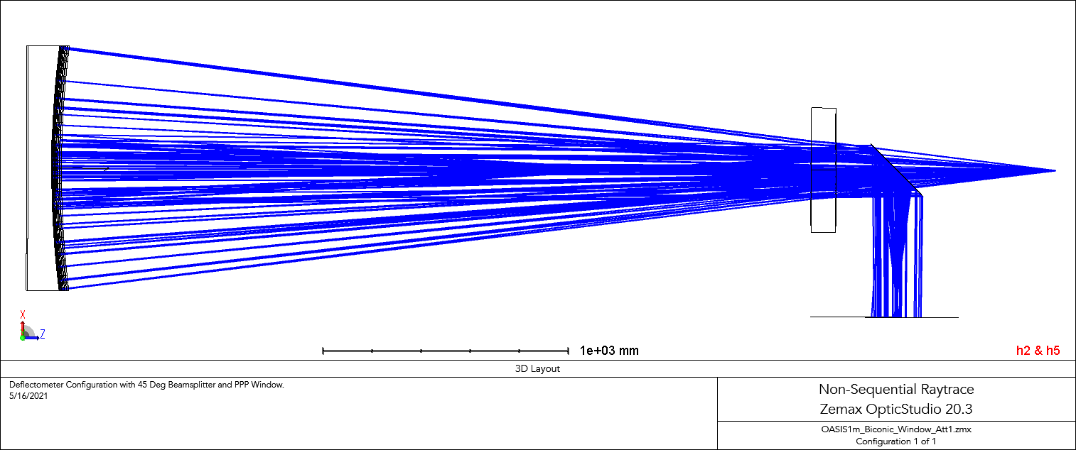
Figure 2.5 In the non-sequential raytrace, an on-axis deflectometer with a pellicle beamsplitter at 45 degrees was used (and a plane parallel plate NBK7 window of limited aperture for research reasons). The initial point source was modeled with an aim sphere equivalent with the camera FOV and traces through the beamsplitter, PPP, then mirror, back through the PPP, then reflects at the beamsplitter. The astigmatic nature of the mirror creates a minimum 'screen size' that reaches is traced to the screen source plane (bottom).
Gravity Sag and Paradigm Choice
The solid body of the inflatable mirror can be simplified to an aluminum ring with ID = 1000 mm, OD = 1150 mm, thickness = 57 mm, and mass of 42 kg. If vertically-mounted, or rested vertically on a similar ring, the axial deflection of the ring in the gravity direction is negligible, but a testing configuration at 3.5 meters away requires a very high ceiling.
If mounted horizontally, the gravity deformation of the ring into an ellipse introduces astigmatism. SolidWorks FEA simulations of the mirror ring resting on its circular rim (touching a flat ground with no penetration contact) or when supported by 6 converging blades to the ring’s center (fixed) both showed an induced ellipticity of \(\epsilon = 0.0002 \). From a first order trial, it was justifiable to ignore effects due to elliptization in further analysis.
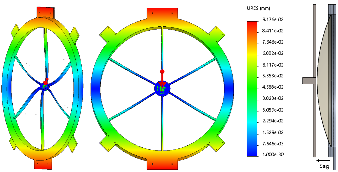
Figure 4. In the first and second subfigures, the bare bones “ferrous” wheel uses six thin blades to support the annular ring. The cross section was approximately 0.75” x 75” and assumed 316 SST sheet. The top blades bend forward, while the bottom blades bend backwards, creating tilt, \(\alpha\). The third subfigure is included to visualize the real estate requirement for a high sag optic.
Because the load \( F_g < 500 N \) is so low, I chose to cantilever the entire optic, taking the path of the spoked ‘ferrous wheel’ design, whose basic form is depicted in Figure 3. The design paradigm embodies the direct intent to rotate the ring and its major loading effect is that the hanging mass bends the top blades forwards and bottom blades backwards, creating tilt. Tilt remains nefarious even in the error budget this UUT-rotating design. Before choosing the cantilevered mount form, I kept an open mind to existing mounts such as the sling mount, the two-point mount, and the “ideal” horizontal mount, but they weren’t very adaptable to the clocking requirement.
Decenter and Digital Center-Finding
Lateral distance between the nominal rotation axis (a calibrated position) and the center of the mounted optic creates decenter. When decenter is present, translation is coupled into rotation motion. I considered embedding an XY decenter adjustment mechanism inside the wheel frame, but this complicates the design by adding additional mount weight and parts.
Interestingly, the digital side of deflectometry’s data processing pipeline takes care of excess decenter. Since the UUT aperture center is digitally identified in pixel space and then referenced to physical space, physical decenter is compensated to precision of the used center-pixel finding algorithm. In this case, a 1000 mm optic represented by a 750-pixel diameter has a pixel pitch of \( \gamma=1.333 mm/px \). In the literature, 0.1 pixels accuracy has been achieved, but 0.5 pixels is more common.
Frame Rigidity and Design Form Baseline
So far, the rotation mount takes the form of a cantilever arm and supports the optic assembly on a short rotation shaft. As for the ground-bolted base, a frame can be constructed from two parallel 45-45-90 triangles made of 700 mm, 700 mm, and 990 mm long 2” profile aluminum extrusion t-slot bars.
Here, the material failure FOS is not as much as a concern as deflections under gravity. For example, a single 2” profile t-slot strut has a stiffness at \(k_{axial}=77.0\ N / \mu m \) at \(L = 700 \ mm \) due to its length and hollowed cross-sectional area. To find the equivalent stiffness of the frame, I simplified all members of the parallel triangle structure to struts (I used \(k_{axial}=EA/L \), \(k_{bending}=12EI/L^3 \), and stiffness \(kcos^2\left(\theta\right) \) for the diagonal strut). The total frame stiffnesses were \(k_{axial}=230.9\ N/ \mu m \) and \(k_{bending}=720.8\ N/ \mu m \), which caused displacements of decenter of \({\Delta d}_{base}\ =\ 1.95\ \mu m \) and despace \( {\Delta z}_{base}\ =\ 0.62\ \mu m \).
In order to reduce FEA simulation time, I represented the complex t-slot triangle base with a blocky 316 SST solid triangle (See the refined model in Figure 6). This block-like triangle is so stiff that the deformation displacement results are essentially just those of the detailed mount/cantilever geometry,\( {\Delta d}_{cantilever/mount}\cong{\Delta d}_{FEA\ result} \) and \({\Delta z}_{cantilever/mount}\cong{\Delta z}_{cantilever} \).
For the final error budget, the displacements of the base and the cantilever/mount are added linearly because they vary together as a function of design. The final calculated \(\Delta d \), \( \ \Delta z \) from deformation are then multiplied by the surface error sensitivities for tallying in the final budget, before RSS’ing with independent errors.
Sensitivity Calculations
Shape Measurement Sensitivity to Rigid Body Frame Motion
In deflectometry measurement, unaccounted system geometry deviation from calibration embeds itself into the final reconstructed shape. Axial miscalibration (despace), or unaccounted departure of the UUT’s position along its optical axis, adds defocus/power because the mirror is closer or further than was accounted in processing. Similarly, lateral miscalibrations (decenter) and tilt of the UUT add astigmatism. In the case of mirror tilt, this perturbation is equivalent to the lateral shift of the camera’s position plus the tilt of the illumination source.
The defocus and power errors introduced by rigid body motion are expressed by taking the partial derivatives of their respective Seidel sums. In order to convert these Seidel aberrations into low-order Zernike equivalents, their terms were equated and solved for. Their conversion factors are listed in the appendix. The sensitivity of measured shape error to rigid body motion is listed in the next table.
| Displacement | Driving Equations | Sensitivities |
| Mirror Tilt | \( \Delta W_{222,\ cam\ lat\ shift\ }=\frac{dr^2}{R^3}\Delta d \) \( \Delta W_{222, \ src\ tilt}=\alpha d \text{tan}\left(\theta\right) \) |
\( \Delta Z_4=4\sqrt3{\ W}_{222,\ cls}\ +4\sqrt3{\ W}_{222,\ st} =172.7\ \mu m \Delta d\ [deg] \) \(\Delta Z_6=2\sqrt3{\ W}_{222,\ cls}+2\sqrt3{\ W}_{222,\ st} =244.3\ \mu m \Delta\alpha\ [deg] \) |
| Mirror Despace | \(\Delta W_{020, \ cam\ ax \ shift}=\frac{r^2}{4ZR}\Delta z \) \(\Delta W_{020,\ src\ ax\ shift}=\frac{r^2}{4ZR}\Delta z \) |
\(\Delta Z_4=\frac{{\sqrt3r}^2}{ZR}\Delta z =28.3\ \mu m \Delta z\ [mm] \) |
| Mirror Decenter | \(\Delta W_{222,\ \ \ dec.}=\sigma_{circle}\frac{D_{physical}}{D_{digital}} \) | \( \Delta Z_4=\frac{{{4\sqrt3\ \sigma}_{circ}D}_{phys}}{D_{digital}}=2.7\ \mu m\ \sigma_{circ}[px] \) \(\Delta Z_6=\frac{{{2\sqrt3\ \sigma}_{circ}D}_{phys}}{D_{digital}} =\ 3.8\ \mu m\ \sigma_{circ}[px] \) |
The rigid body displacement occurs comes from 2 independent effects: finite deformation (a function of design and can only be minimized by the design) and part manufacturing tolerances. For example, both tilt from deformation and manufacturing wedge produce Z4 and Z6 error due to rigid body motion with equal sensitivity, but they vary independently and add in quadrature in the final budget.
Clocking Certainty
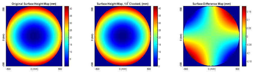
Figure 5. Over a 45-degree rotation of a circular optic, the amount of Z5 and Z6 switch. This is because the azimuthal frequency of astigmatism is 2θ. The original biconic shape (has lots of Z6) is plotted and is visually indistinguishable with its shape rotated by 1°. When subtracted, Z5 reveals itself as the dominant difference between the two after the small rotation.
For a nominally rotationally symmetric optic, clocking errors are not a threat to accuracy. However, for a biconic optic, clocking matters because of the substantial excess astigmatism detected in the measurement result. Surface error is a function of the partial derivative of the inherent astigmatism of the test surface with respect to clocking angle. I simulated the induced surface error by clocking the biconic shape by 1° in Matlab, resizing and interpolating to obtain the same map dimensions, and then subtracting the maps. Fitted into Zernike’s using SAGUARO’s implementation, the results and difference map are shown in Figure 5, while the sensitivities are in the following table.
| Driving Equations | Sensitivities |
| \( \Delta W_{clocking}=\theta_0\frac{\partial C_5Z_5}{\partial\theta}+\theta_0\frac{\partial C_6Z_6}{\partial\theta} \) | \( \partial Z_5 = \Delta Z_{5,\ matlab \ sim, \ 1^\circ} = 74.21 \ \mu m \Delta\theta \ [deg] \) \( \partial Z_6 = \Delta Z_{6,\ matlab \ sim, \ 1^\circ} = -1.29 \ \mu m \Delta\theta \ [deg] \) |
Shape Measurement Sensitivity due to Membrane Deformation
The shape of the inflatable membrane mirror is sensitive to its inflation pressure. As a general trend, surface power increases with internal pressure, but power increases per unit inflation (1 mpsig, or 1 milli – pounds per square inch - gage) diminishes towards pressures. Simultaneously, astigmatism in both axes change with pressure, also with diminishing returns at higher pressures. The experimental data in the table below paves the relationship for finite temperature changes and pressure leaks.
| Pressure Change (per 1 mpsig) | \( W_{51}-W_{50} \) | Pressure Sensitivity |
| Z4 Defocus/Power | 5.60 E-02 | \( \tfrac{\partial Z_4}{\partial P} = \tfrac{\Delta Z_{4, \ P}}{1 \ mpsig} = 55.95 \ \mu m\) |
| Z5 Oblique Astigmatism | -8.26 E-05 | \( \tfrac{\partial Z_5}{\partial P} = \tfrac{\Delta Z_{5, \ P}}{1 \ mpsig} = -0.083 \ \mu m\) |
| Z6 Vert. Astigmatism | 1.63 E-02 | \( \tfrac{\partial Z_6}{\partial P} = \tfrac{\Delta Z_{6, \ P}}{1 \ mpsig} = 15.22 \ \mu m\) |
Temperature Change
Starting with the ideal gas law, we can deduce the temperature change for a fixed volume of gas will also change its pressure. The incremental pressure change can be multiplied by the sensitivities in Table 5 to obtain the sensitivities to temperature, for the nominal inflation pressure at 50 mpsig, to obtain the sensitivities of Table 6.
| Driving Equations | Sensitivities |
| \( \Delta P_{\Delta T}=P_2-P_1=\frac{P_1\left(T_1+\Delta T\right)}{T_1} \) \( \Delta Z_{n,T} = \frac{\partial Z_n}{\partial P} \Delta P_{\Delta T}\) |
\(\Delta Z_4=10.247\ \mu m\ \Delta T[K] \) \(\Delta Z_5=-0.015\ \mu m\ \Delta T[K] \) \( \Delta Z_6=-2.788\ \mu m\ \Delta T[K]\) |
Temporal Pressure Drift
More candidly acknowledged as the gas leak rate, we have experimentally measured and rounded up to a conservative leak rate of up to 2 mpsig per hour. A similar conversion yields the sensitivity in Table 7. The pressure drift is therefore dependent on the time taken to make a deflectometry measurement, which is nominally 30 seconds. With all the sensitivities of rigid body displacement and membrane shape deformation calculated, it appears that the most influential factors to limit are rigid body tilt \( (172\ \mu m \ Z_5/[1 ^\circ] \) and \(244 \ \mu m \ Z_6 /[1 ^\circ] \)) and rigid body clocking \(( 74.2 \mu m \ Z_5/[1 ^\circ] \)).
| Driving Equations | Sensitivities |
| \(\frac{\partial P}{\partial t}=\frac{2\ mpsig}{hr}=\frac{0.0005\ mpsig}{s} \) \( \Delta Z_{n,leak} = \frac{\partial Z_n}{\partial P} \frac{\partial P}{\partial t} \Delta t\) |
\(\Delta Z_4=3.11 E-02\ \mu m\ \Delta t[s] \) \(\Delta Z_5=-4.55 E-05\ \mu m\ \Delta t[s] \) \( \Delta Z_6=-8.45 E-03\ \mu m\ \Delta t[s]\) |
Analysis of Final Design
Top Level Assembly
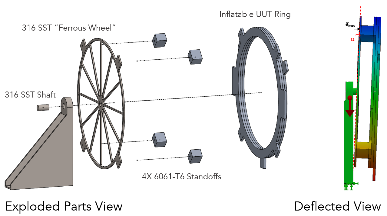
Figure 6. In the top-level look, the spoke wheel mount which mounts through standoffs to the inflatable UUT ring. The attachment mechanism is simply ½” diameter bolts in preload through the rectangular UUT tabs and through the spoke wheel tabs. The SST shaft is 43 mm from the distant edge of the spoke wheel. The representative triangular support base, actually made from 2” square profile aluminum extrusions, is bolted to ground.
This design, exploded in Figure 6, takes advantage of the fact that we can digitally compensate for decenter. This allows us to leave some slop in the through holes without needing to worry about alignment during assembly.
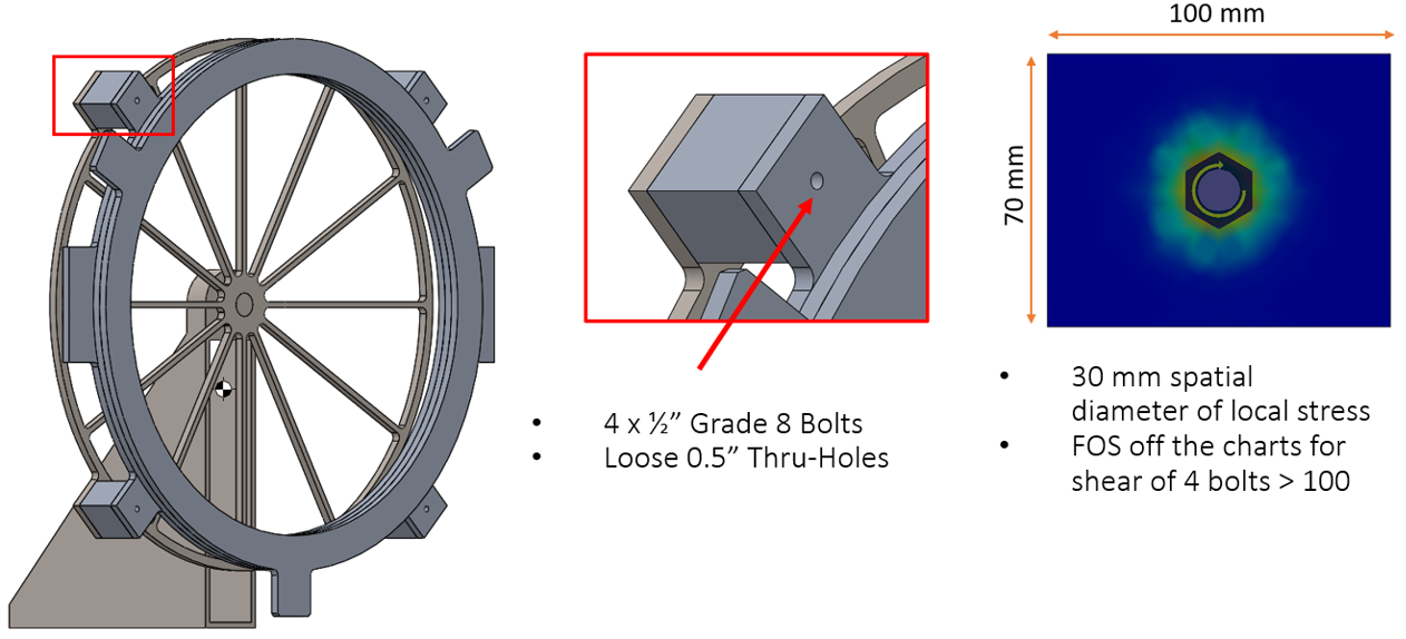
Figure 7. An FEA analysis was done between clamped rectangular plates with a ½ inch bolt with an equivalent size nut at the other end. I used a curvature-based mesh, fixed one plate at its bottom edge, and then used non-penetrating contacts between the plates because that was required to run the ‘bolt connector’ constraint. I used bolt tightening parameters and suggestions from Engineer’s Edge.
Figure 7 shows that the stress distribution of the bolt torqued at 2.5 N*m does not bleed outside the rectangular tab. It has a ~20 mm ‘radius of influence’ at which stress drops from its highest value below 5% of its highest value and more confidently, a ~30 mm radius where local stress effects from the bolt aren’t really seen. Because this diameter of influence does not extend past the rectangular tab, it does not disturb the O-Ring seal gland beyond the tab with a radius of 40 mm, which was required for form/survival. The length of the machined 6061-T6 aluminum standoffs leaves 100 mm of maximum of sag for a bursting optic, so it meets that form requirement as well. If we fix the clocking accuracy to fixed number such as 0.5 degrees, the clear objective of the design is now to minimize tilt, \(\alpha\). It was nice to design the spoke wheel just around this factor basically exclusively.
Spoke Wheel Design for Tilt
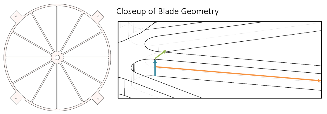
Figure 8. The spoke hub mount uses numerous 316 SST blades. The blade width is in green, blade height in blue (critical!), and blade length in orange.
What dominates deformation-induced tilt from the spoke wheel is bending of the spokes. I originally had a 3/4” inch thick spokes cut from a waterjet, but the time to cut through such a thick piece is long. I reduced this thickness, or blade height, to ½ inch while maintaining deflection of 133 um, which produces 13 um of Z4 and 18 um of Z6.
Increasing the number of blades increases the bending stiffness, but if the width of each blade is decreased to approximately preserve mass, the overall deflection doesn’t change much. However, a larger number of blades increases the manufacturing time, which directly increases waterjet manufacturing time and cost. The advantage of more blades symmetrically placed about the axis is that it handles loads at different rotation orientations more evenly. When a blade is aligned with the gravity vector (pointing directly down) versus when it aligns with bisector of two blades differs by as much as 15 microns decenter when I used three blades in informal, iterative FEA analysis. It is reduced to about 2.5 micron of variation for 12 blades, with equal total mass. Unfortunately, this incremental difference in decenter variation doesn’t matter compared to the 133 micron decenter dictated by digital centration.
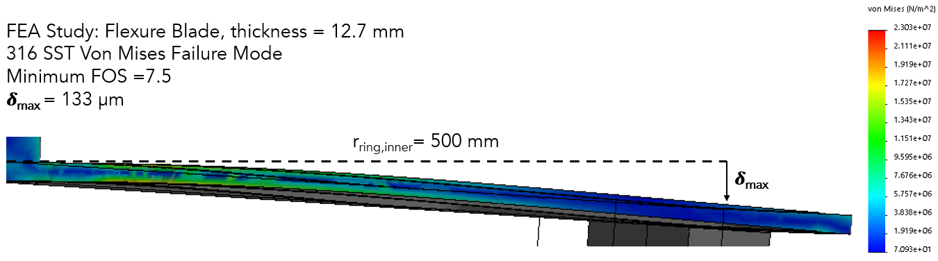
Figure 9. The FEA for the blade was done like this. This is the half cross section. Blade made of SST. I also tried aluminum and the deflection was ~500 microns more. This is a rotated view of one blade being bent.
Examining the FEA of a gravity load in Figure 8, the blades that experience the most stress are the ones at the top and bottom ones. In this study, I used a control mesh at all the edges and innermost tiny corners. A 1.5 mm control mesh at these interfaces was used, while the characteristic dimension of the blade cross section was 12.7 mm x 12.7 mm. The center cantilever shaft top was fixed, and the standoffs and UUT ring frame were treated as bonded because of the clamp preload applied by the bolt. The minimum factor of safety was 7.5 under the regular gravity load when the gravity vector was aligned with this single blade. Again, this bending matters for optical performance (well, surface reconstruction accuracy) because the deflection matters. Final values for the design choices of the spoke are tabulated in Table 8.
| Design Choice | Design Value |
| Number of Blades | 12 |
| Blade Width (Parallel to Bending) | 0.5 in |
| Blade Height (in direction of Bending) | 0.5 in |
| Blade Length | 480 mm |
| Material | 316 Sheet SST |
Closeup of Temperature and Survival
Now what remains is a study for the survival as temperature is increased or decreased by 30K. The primary design fear was that the thin blade spokes increase in length during the temperature. As expected, the ends of the blades had the most stress, particularly at the nexus of all spokes. However, the FOS was still met for both temperature extreme cases.
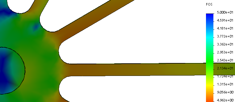
Figure 10. FOS of the spoke hub nexus, meeting the minimum FOS = 3, for both bilateral temperature load cases and the gravity load. The same control meshes were used at both sides of the hub mount, and the FOS > 3 all the same for both cases.
Manufacturing Considerations
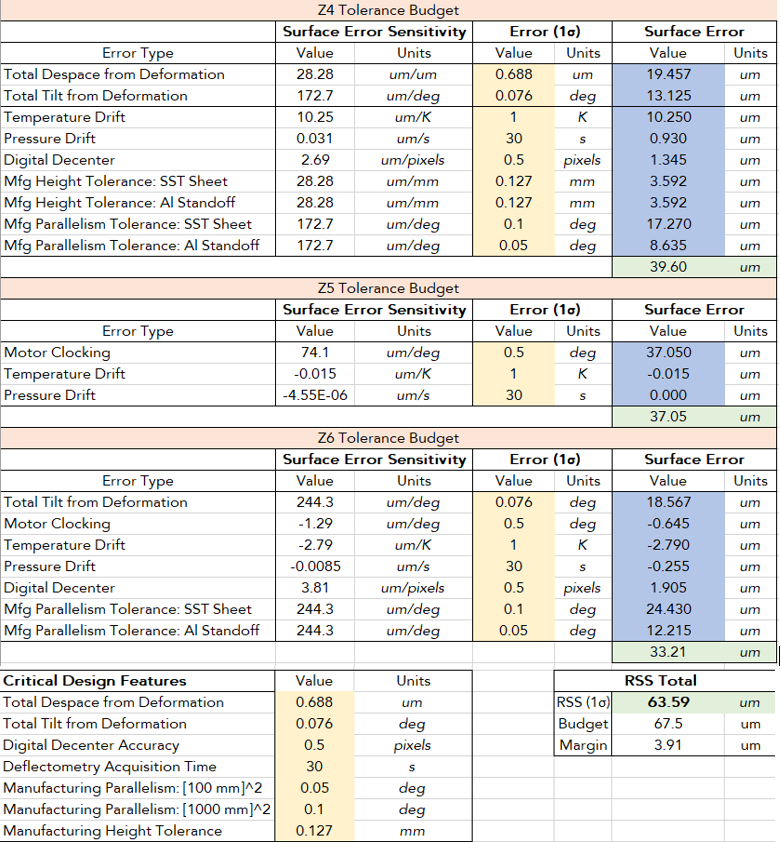
With deformation during static load handled, now rigid body ‘motion’ due to part manufacturing tolerances must be considered. With the entire spreadsheet filled out for deformation + temperature + pressure + clocking, the tolerance limits can be played with to take advantage of the remaining budget.
Total Despace – when assembled, the height uncertainty stackup of the 1m x 1m (huge flat thing, inconvenient to workhold) height of the sheet metal and the aluminum standoffs (small, very fixturable workpiece) contribute to despace. It is unfortunate but I think the huge sheet must be faced off with an endmill before waterjet cutting. Assuming both parts use different milling machines, the effects of their tolerances add in quadrature. A standard 0.005” tolerance (0.127 mm) was well within the budget.
Total Tilt/Parallelism – any rigid body tilt was devastating because the sensitivity was 244.3 um/deg. Parallelism units are specified differently in GD&T, but I am going to specify it here in terms of angle between two best fit planes at each side of the nominally flat surfaces. Getting good parallelism for the huge sheet is likely an ugly and slow process because you have to repeatedly fixture, mill, and flip. I specified that the smaller standoff needed 0.05° of parallelism, while the larger sheet was afforded 0.1°. With that, the budget was met with 3.91 um to spare of the allowed surface measurement error.
Error Budget and Concluding Remarks
At last, the full contributions of base frame and mounting deformation, environmental contributors such as temperature and pressure drift, and manufacturing tolerances are shown in the Table 8.
Some reflections on this project are that unaccounted system geometry can be devastating towards surface measurement error accrual, particularly tilt and clocking. In a real measurement, both must be carefully and measured out of a system so that sufficiently accurate representations of Z4, Z5, and Z6 are obtained. But dually, if a laser tracker can be used to discover a system’s geometry, this method can be very powerful to measure the figure of highly-sloped and varying surfaces.
In this project, no such external measurement instrument was available, and any physical deviations from a rigid, perfectly-manufactured mounted inflatable optic was said to cause error. Such a case is typical for quick-and-dirty deflectometry measurements with a single reference point for the UUT relative to the deflectometer system. In this scenario, it was important to control excess tilts from deformation and part parallelism tolerances.
Clocking accuracy is left to the motor attached at the opposite end of the shaft, and likely very controllable with an ordinary controller and encoder. Some other angles to make more room in the budget are to reduce system acquisition time, seal the pressure leak interface, and improve the digital decenter algorithm beyond Matlab’s standard precision. If more time was allocated for the project, I would have liked to include all of these optimizations and also tolerance the procedure by which the external reference geometry of a deflectometry measurement are determined.
References
[1] Walker, C., Kulesa, C., Smith, I. S., Perry, W., Kim, D., Palisoc, A., Cassapakis, C., Crowe, D. and Pierce, D., “Orbiting Astronomical Satellite for Investigating Stellar Systems (OASIS)” (2019).
[2] Meinel, A. B., “Inflatable membrane mirrors for optical passband imagery,” Opt. Eng. 39(2), 541 (2000).
[3] Quach, H., Berkson, J., Sirsi, S., Choi, H., Dominguez, R., Duffy, B., Lesser, D., Takashima, Y., Palisoc, A., Walker, C. and Kim, D. W., “Full-aperture optical metrology for inflatable membrane mirrors,” 20 (2020).
[4] Evans, C. J. and Kestner, R. N., “Test optics error removal,” Appl. Opt. 35(7), 1015 (1996).
[5] Parks, R. E., “
[6] Noll, R. J., “Zernike Polynomials and Atmospheric Turbulence.,” J Opt Soc Am 66(3), 207–211 (1976).
[7] Vukobratovich, D., “Mounting Large, Horizontal-Axis Mirrors,” 115–140 (2015).
[8] Shangkun Wang, Yansong Wang, H. G., “Sub-pixel Measurement System of Circle Outer Diameter Based on Zernike Moment,” DEStech Trans. Comput. Sci. Eng.(aiea), 894–903 (2017).
[9] Su, T., “Aspheric Metrology for Non-Specular Surfaces with the Scanning Long-Wave Optical Test System” (2014).