Henry Quach
Optical EngineerKinematic Supersonic Funky Fresh
Practical 3D Printed Kinematic Couplings
I was insanely excited to finally need custom k-couplings for my own research. I needed to obtain highly repeatable positioning between metrology setups at different stations (i.e. home, lab, CMM). I really liked the V-Groove and cylinder geometry, which was praised by Douglas Goodman's papers "Cylinders in V's: An optomechanical methodology" [1997] and "More Cylinders in V's" [2000].
From those papers, I designed my own preloaded kinematic mounts with about ~$5 of hardware from McMaster-Carr and 3D printed parts. My coupling's was tested and shown to have an rms angular repeatability of ~47 arcseconds.
Unable to afford custom machined V-Grooves or flats, I went to McMaster-Carr and bought stiff precision components such as bearing balls and dowel pins. Both are easily accurate up to 0.0002" and relatively cheap. For example, a pack of 50x 1/8" tight-tolerance hardened 440C SST bearing balls is just ~$7 on McMaster and 10x 1/4"x3/4" 18-8 SST dowel pins for ~$6. My design specifically required a custom k-mount because I needed an annular core area (uncommon) and had basically no budget.
Quasi-Kinematic Design
When you are looking to obtain highly repeatable positioning, you turn to kinematic design. The principles of kinematic constraint assert that that infinitely rigid bodies have six degrees of freedom and that contact with another body reduces one degree of freedom. By reducing the possibilities of motion with point contact, kinematically-considered designs increase the degree of determinism for the remaining unconstrained DOFs.
Theoretically, point contacts experience infinite stress at their infinitesmally small contact area. However because we have finite stress moduli, the point contact geometry deforms under load to a non-point contact area which distributes the force accordingly. The deformation into a non-point contact areas is predicted by Hertzian stress theory and is engineered into semi-kinematic designs which use line contact or quasi-point contact with very small-areas. Dr. Alex Slocum's work explains the theory and clever management of Hertzian contact stress in great detail.
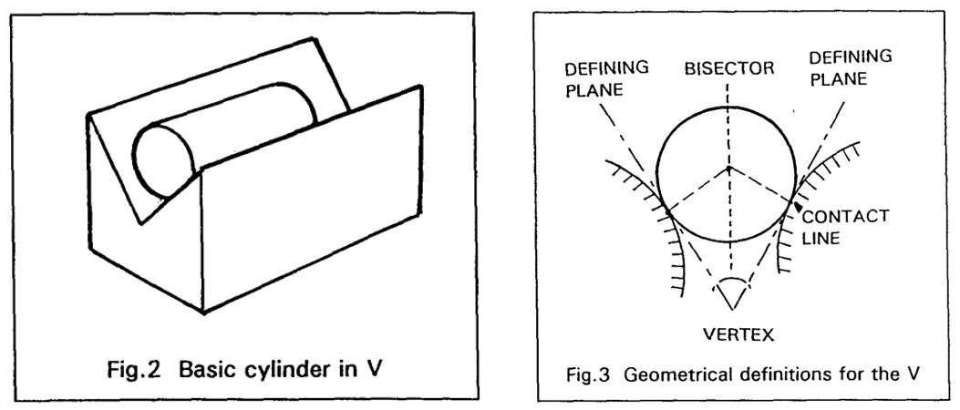
Goodman's work went into practical areas of implementation and I liked the two cylinder, one ball geometry in particular. From his texts and some advice from previous colleagues, here's what I designed for:
1. Maximize the vertex angle. This increases the contact angles between the spheres and cylinders to maximize stability. You can think of the reaction force vectors being distributed to resist side-to-side motion better with a larger angle.
2. Choose the largest diameter spheres and cylinders. This increases the contact angles between the spheres and cylinders to maximize stability. You can think of the reaction force vectors being distributed to resist side-to-side motion better with a larger angle. In light of higher contact stress at larger angles, we want shallower slopes to resist the local deformation and prevent yield (note: nonrepeability!).
3. Choose harder steels. I went with 300-Series steels because the are also resistant to corrosion. Note that corrosion and the thin oil of film on human hands reduces the determinism of the point-contact interaction.
4. Print thicker parts with >30% infill. These parts need maximum stiffness too and to not yield. We are allowed to use 3D printed parts because at a fixed temperature and as long as load doesn't change or induce yield, the ball-cylinder interfaces act deterministically as they usually do - exactly what we want.
Implementation & Assembly
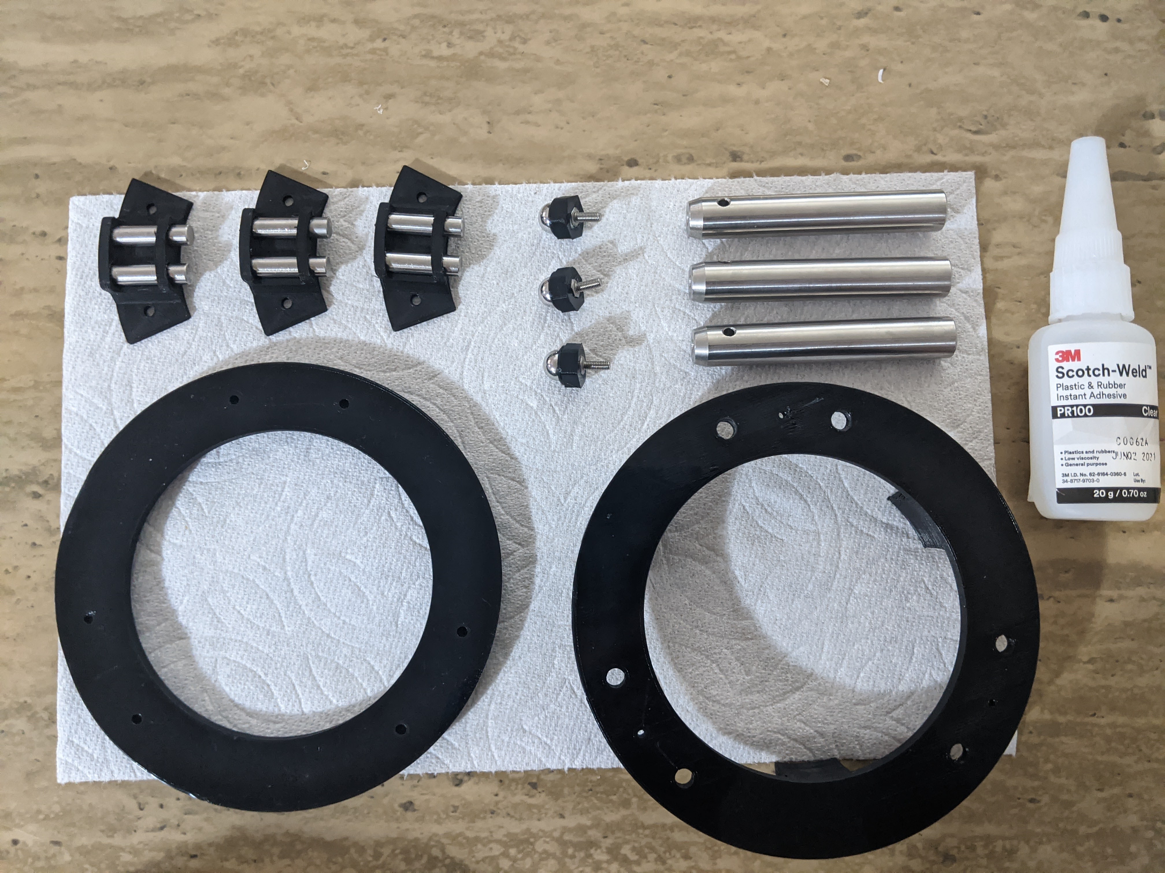
Following those criteria, here are my quasi-kinematic interfaces! I chose 3/8" SST balls and 3/16" SST cylinders. I used 3" optical posts from Thorlabs as my preload since I had no denser materials in excess to use. Preload is required to ensure that contact is constantly in compression and not perturbed by small forces. Part of my design was to have the balls adjustable so that tip/tilt could be approximately modified.
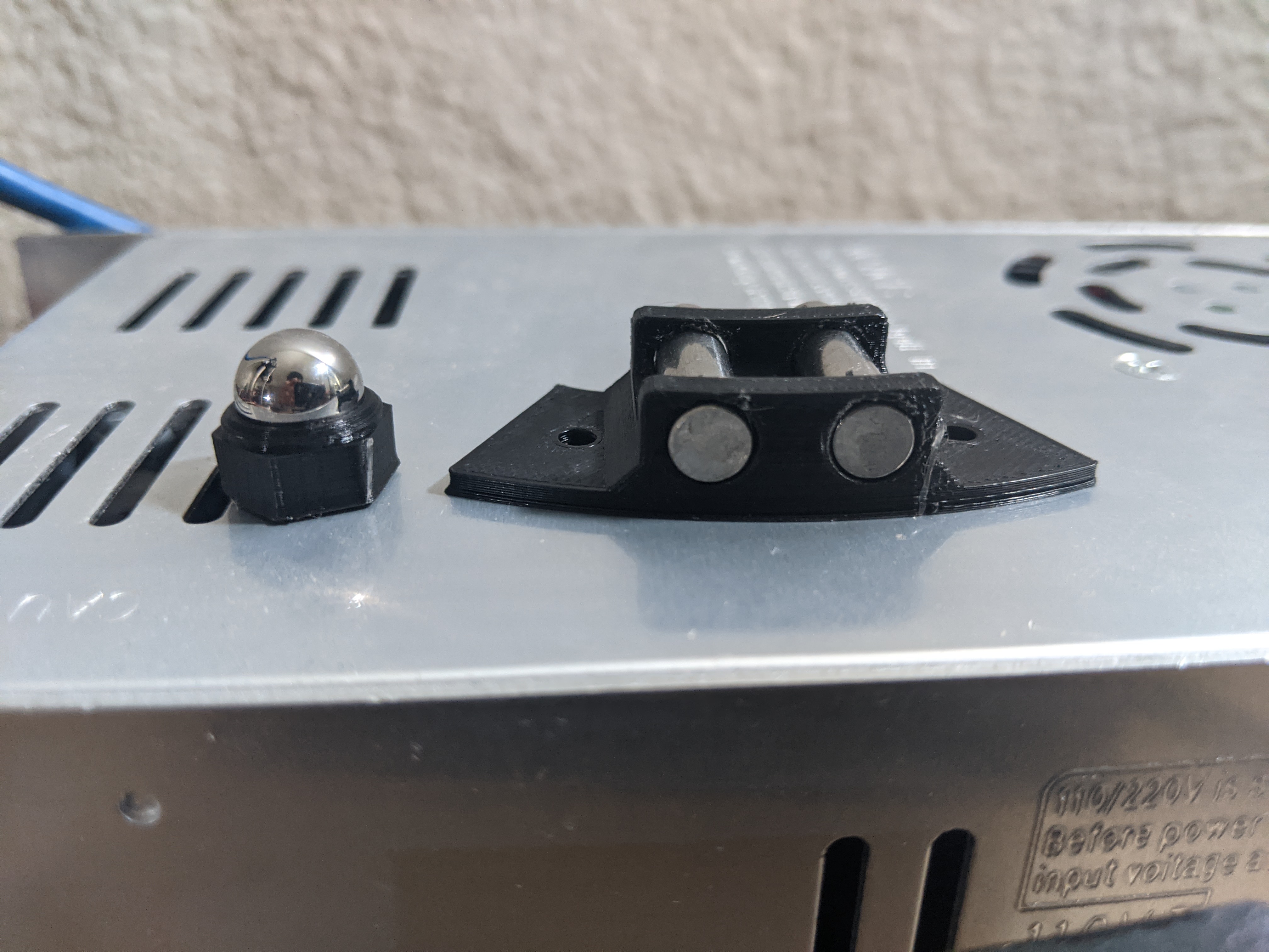
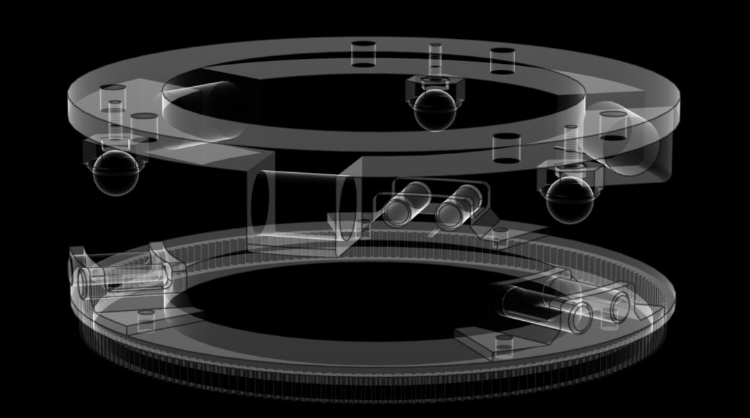
The hexagon face of the ball interface was chosen so I could use my nifty torque wrench to adjust the ball height. Look how distant the two cylindrical line contacts are! I used an absurd vertex angle of 80 degrees.
Laid out, here's what it all looks like.
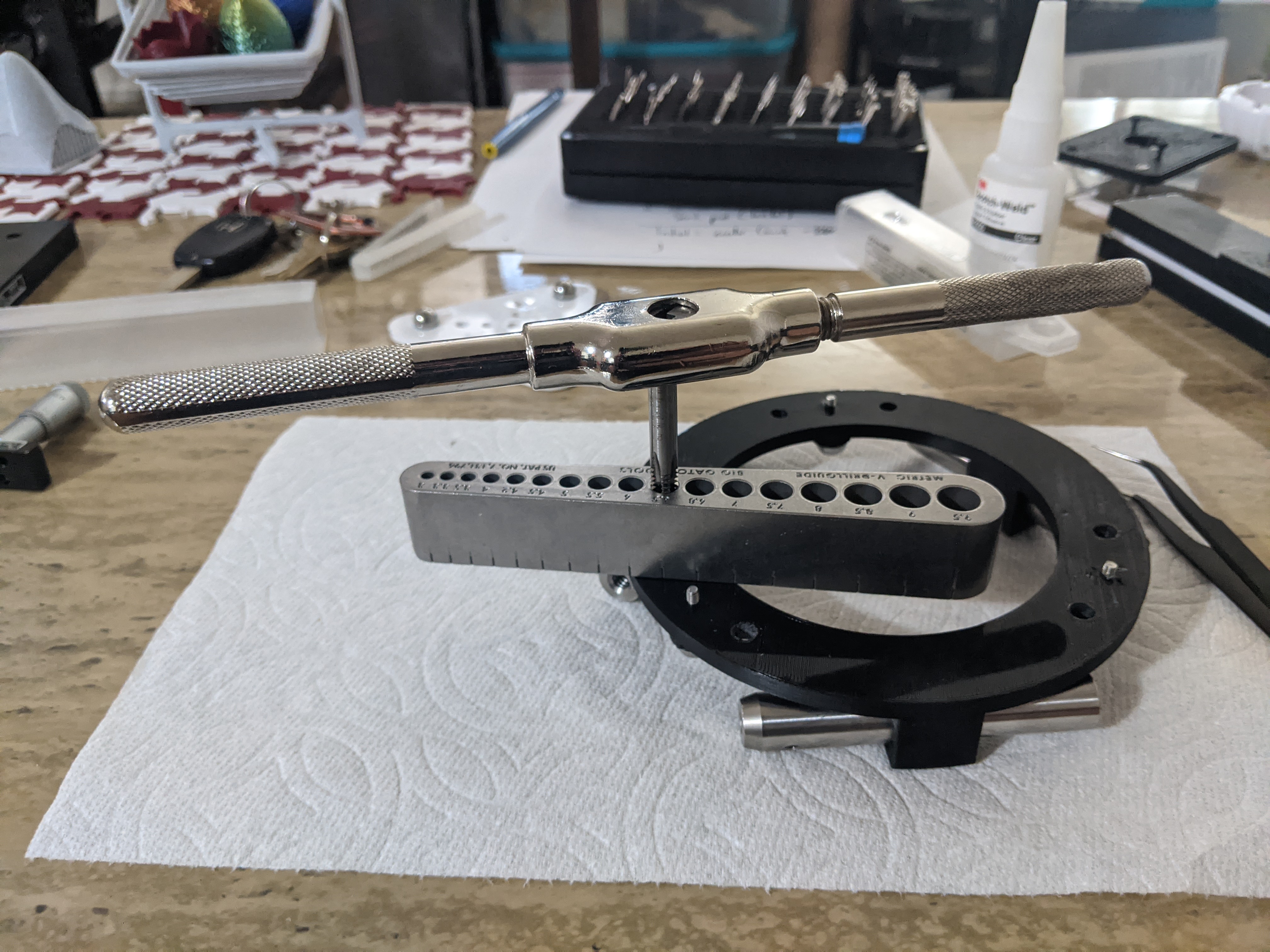
I used a tap and die and a tool-steel alignment guide to get straight holes for the ball-interface assembly. Actually this doesn't matter so much because cosine error isn't critical - these holes are for the tip/tilt adjustment anyway.
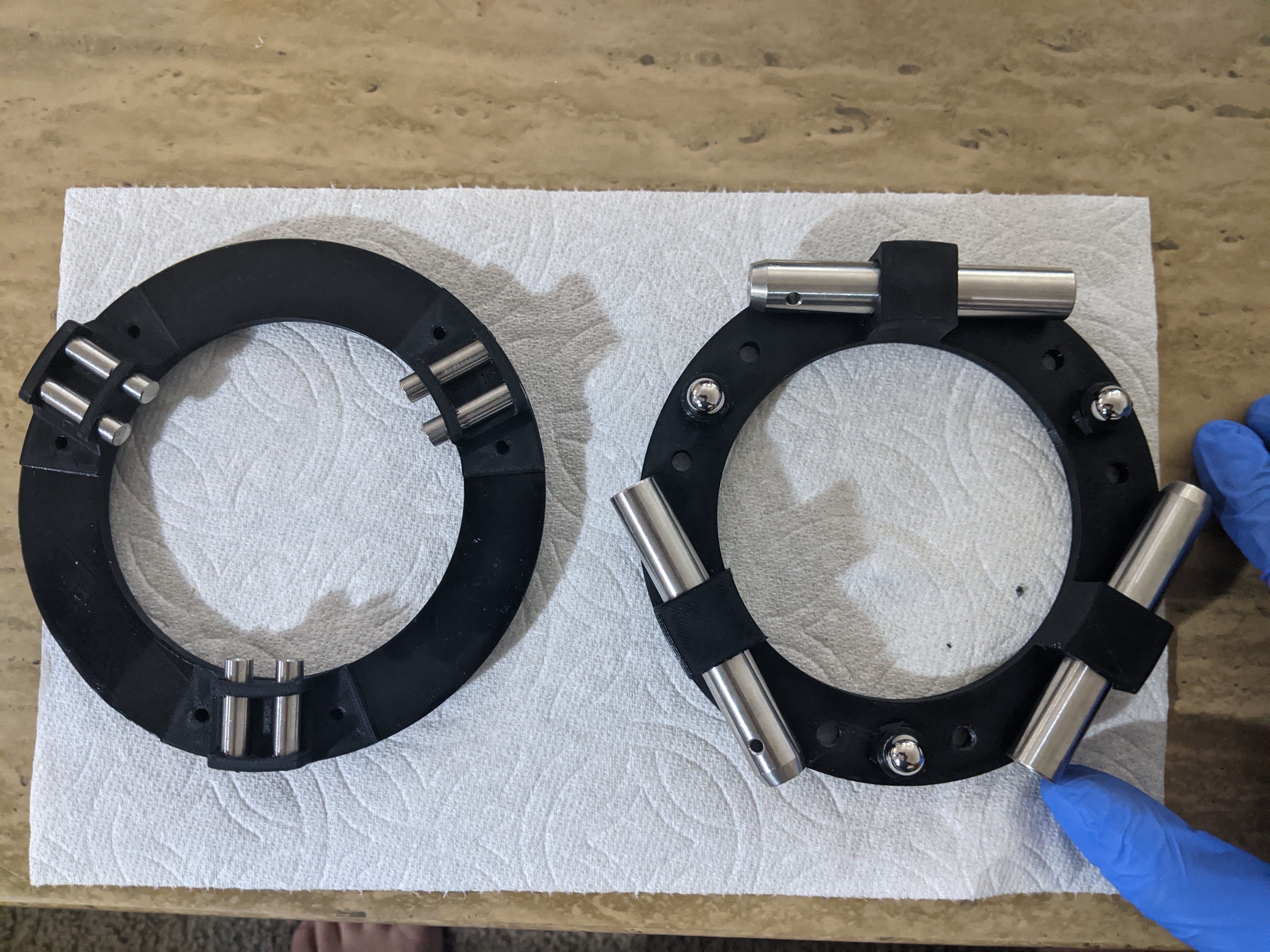
Full assembly of both mating halves. It snaps together so amazingly well with the preload. If I had chosen a 400-series steel (martensitic; hardened), I probably could have made some nice elegant magnetic preload mechanism.
Repeatability Testing
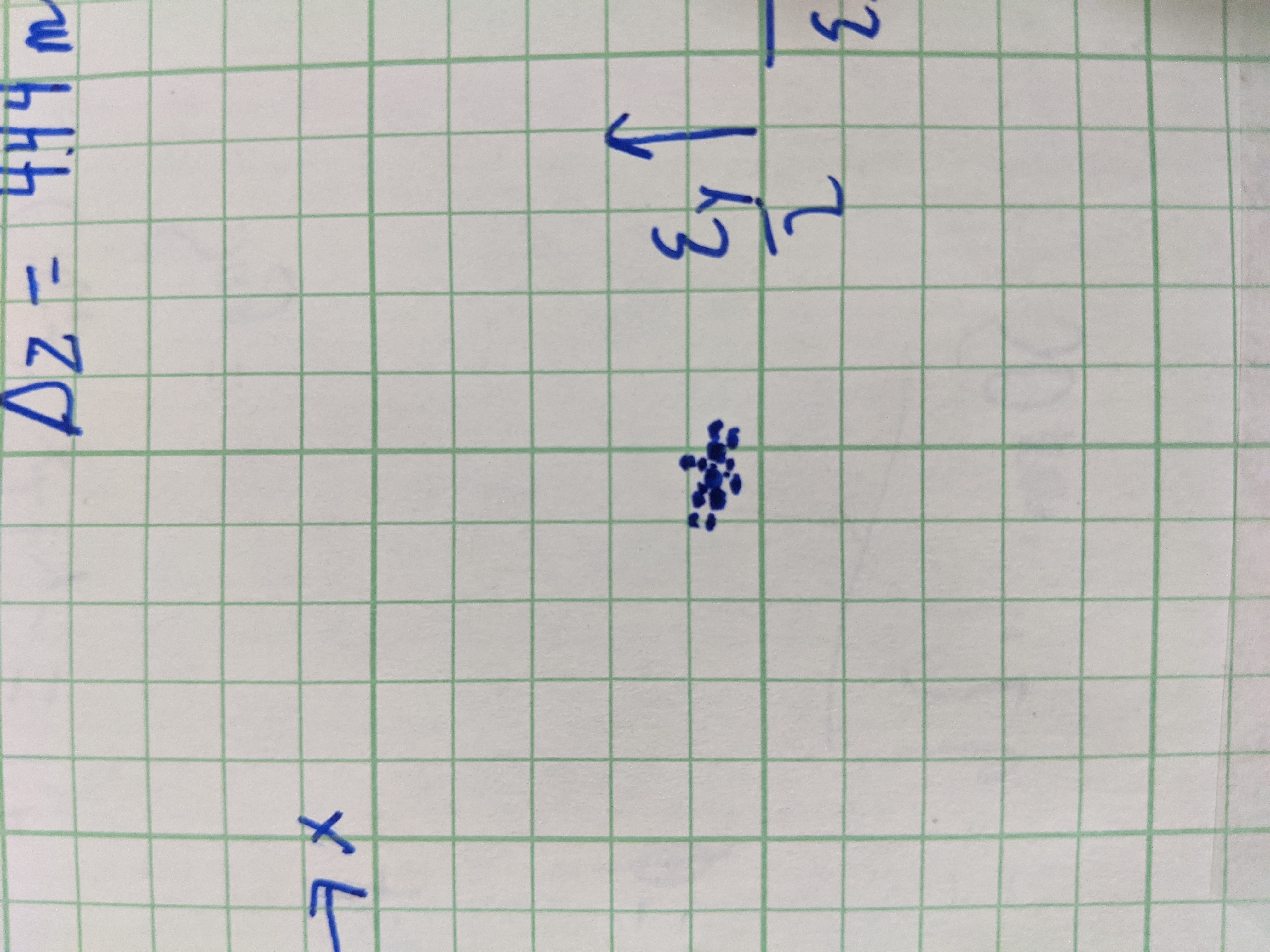
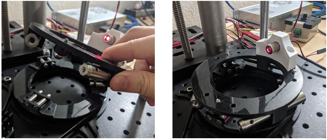
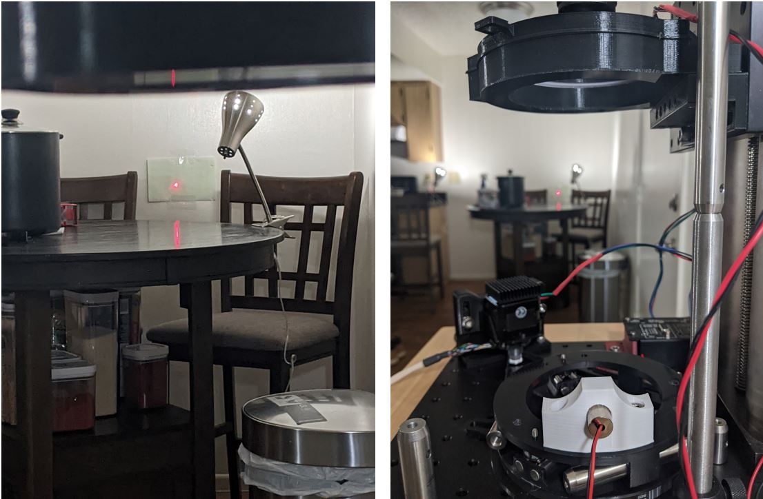
I conducted repeatability testing by mounting a diode HeNe laser to the upper assembly. Collimated, the laser creates a spot at a piece of paper taped to the wall ~4.4 meters away. I placed and replaced the mount again and again, marking a dot where the beam landed.
Here's what the beam spot at 4.4 meters looks like.
And here's what the spread of spots looks like. The radius of this ellipse is about 3.80 mm. Not bad right? Taking the arctan and then using ~30 spots, we get an average of 66.96 arcseconds, but a standard deviation of 46.8 arcseconds. Not bad for a 3D printed mount right???