
Henry Quach
Optical EngineerSchott Glass Polarimetry
Introduction
Our human eyes are evolutionarily-polished light sensors that can perceive scene brightness to 150 photons of luminous flux, resolve objects to 1 arcsecond, and distinguish color down 1 nm of wavelength separation. But our eyes have no mechanism to detect polarization (unless you strongly express the gene for Haidinger's Brush).
I suspect this is why that polarization can feel like a distant concept even among optical scientists. Polarization is the oscillation of electric field vector in the transverse plane, but this can get mixed up with other geometrical depictions in optics. For example, a plane wave can be circularly polarized. Indeed, the surface of constant phase is flat, while every point on that surface has an electric field orientation described by the trajectory of a point along a helix. Alternatively stated, the procession of the electric field vector traces out a circle over time. The state would be fully described by \( \vec{E}(\vec{r},t)=E\cdot exp[j(\vec{k}\cdot\vec{r}-\omega t + \phi_0)]\hat{a} \), where the polarization vector is \(\hat{a}=[1, \pm i]/\sqrt{2}\). Really, any arbitrary polarization state could characterize an arbitrary point across the surface of a given wavefront shape.
Polarization just has a way of seeming unimportant until it becomes all important.
For my own understanding, I wanted to demo and narrate interesting polarization properties of real materials and geometries with a novel demonstruction subject - a shot glass.
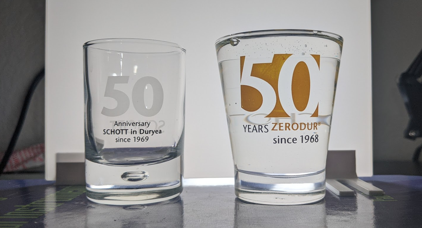
Schott AG, the original distributor of N-BK7 (crown borosilicate glass), hands shot glasses out every year at the optics career fair. These two Schott glasses were obtained in the Fall of 2018 and Fall of 2019.
The Fresnel Aberrations
The language of commercial polarization elements speaks of a fast, slow, transmission, and extinction axis, but the parlance of polarization science prefers the word eigenpolarization. This nomenclature descends from spectral theory - you know, the linear algebra formalism with eigenvalues, eigenvectors, and whatnot. In the same way that a special vector called an eigenvector can pass through a linear system unchanged except for a scale factor, an eigenpolarization \(\textbf{E} \) is a polarization state passes through a simple optical system \(\textbf{J} \) unchanged except for a scale factor \( \xi\) (which can also be zero or imaginary).
There are two orthogonal eigenpolarizations for every ideal optical element - one that transmits max amplitude or phase change, and one that transmits minimum amplitude or phase change. Any fully polarized incident wave is spanned by the two eigenpolarizations of the ideal optical element. If \(\xi\ = Re[\xi]\), then this scale factor change represents a change in wave amplitude, while a pure imaginary factor \(\xi\ = Im[\xi]\) represents a phase change. Please note that in this case, the ideal optical element is homogenous, and so \(\textbf{E}_1 \perp \textbf{E}_2 \). Imhomogenous systems do not have eigenvalues with meaningful interpretations and require decomposition with the SVD.
$$ \textbf{J} \cdot \textbf{E}_1 = \xi_1 \textbf{E}_1 = \rho_1 e^{-i\phi}\textbf{E}_1 $$
$$ \textbf{J} \cdot \textbf{E}_2 = \xi_2 \textbf{E}_2 = \rho_1 e^{-i\phi}\textbf{E}_2 \\ $$
As an arbitrary fully polarized wave passes through some optical system, we can decompose it into the basis set spanned by its eigenpolarizations. Then we can use multiplication (convenient and allowed by our eigenanalysis) to obtain the modification of each decomposed basis vector, and sum the two separately-propagated states to get the final polarization output state. Real-valued difference in the two eigenvalues results in preferential attenuation, or diattenuation, while an imaginary-valued difference results in a phase delay between the two orthogonal eigenpolarizations called retardance.
| Element | Polarizer | Retarder |
| Mechanism | Flux transmission is polarization dependent. \([W/m^2]\) | Phase delay between two components is polarization dependent. \([deg, rad, nm, waves]\) |
| Overall Effect | Diattenuation depends on thickness. | Retardance depends on thickness. |
| Material Property | Dichroism – different absorption between eigenpolarizations. | Birefringence – different OPL between eigenpolarizations. |
| Jones Matrix | Hermitian | Unitary |
| Eigenvalues, \(\xi\) | Exclusively Real | Exclusively Imaginary |
| Measurement | A direct measurement can be made of the transmission flux. | A direct measurement cannot be made of the phase difference. |
| Precise Axis Nomenclature | Transmission Eigenpolarization | Fast Eigenpolarization |
If you placed an ideal linear polarizer in front of an unpolarized scene or source, the amount of light would be half of the original because only one eigenpolarization is transmitted. If you placed an identical polarizer further up and orthogonal to the first, then naturally you would expect no light to get through. But look at this image of a shot glass between two crossed polarizers. The surrounding background goes to black as expected but there's a cross pattern in the shot glass. What's going on?
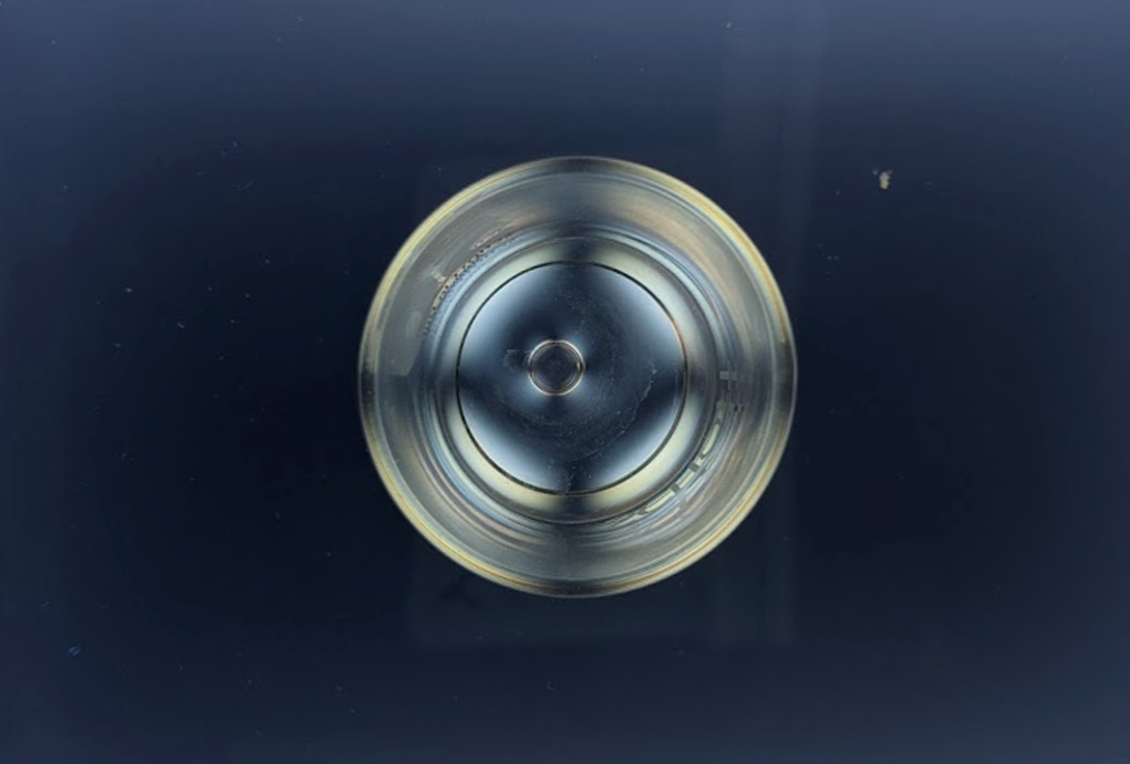
The legendary Maltese Cross is observed between two dichroic polarizers. The Maltese Cross is aligned with the two polarizers' shared eigenpolarization axes. If the polarizers are rotated, the cross will follow. There is a bubble of air trapped between the upper and lower surface of the shot glass floor which disturbs the spatial vividity of the cross pattern.
This spatial pattern is known as the Maltese Cross. The cross is created by light leakage at the edge of the shot glass base. The base of the shot glass is not flat, but rather, approximately radially symmetric and concave. The light rays passing through the lower sheet are generally striking the sloped concave surface at a nonzero angle of incidence (AOI). By the Fresnel Equations, we know that the amount of transmitted and reflected light depends on both the AOI and whether incident light is parallel to the plane of incidence (p-polarized) or perpendicular (s-polarized), and in general, these two basis vectors form a complete basis set for any incident light, \(\textbf{E} = E_s\hat{s}+E_p\hat{p} \), where \(E_s\)and \(E_p\) are generally complex. Looking at the plots of \(r_s, r_p, t_s, t_p \), we know that there is diattenuation and retardance because amplitudes differ between the \(s\) and \(p\) polarizations at all AOI's except normal and grazing incidence. Thus, any optical element (even a plane parallel plate) at non-normal incidence to a beam will exhibit geometry-dependent diattenuation and retardance due to these polarization effects, called Fresnel Aberrations.
If we insert a spherical lens between two crossed polarizers, the effect of Fresnel Aberrations is readily apparent. If unpolarized light passes through a first polarizer (let's say its eigenpolarization is "vertically oriented"), then the exiting polarization state is simply that eigenpolarization. If we draw a chief ray from each object point of the illumination source through the lens, then we can see that the AOI at the curved interface varies with pupil position. Pupil positions along a vertical and horizontal cross reveal no light leakage at the image because the refracted chief ray through these transverse planes retain a polarization state that is orthogonal to the eigenpolarization of the second polarizer. Thus, light is fully extinguished precisely through the cross.
However, all pupil positions not along this cross will refract along other meridional planes and contain local \(\hat{s}\) and \(\hat{p}\) polarization components that are simultaneously non-zero relative to the second polarizer. Thus, not all light will by extinguished by the second polarizer since its set transmission eigenpolarization. It happens to be that the coupling is strongest at the 45 and 135 degree diagonal positions and grows with the pupil coordinate position \(\rho\) as a function of \(\rho^4 \). Such explains the spatial appearance of the Maltese Cross.
Circular Birefringence
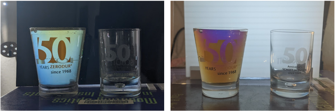
The conical '50 Years Zerodur' glass is placed between two polarizers. As the polarizer closest to the camera is rotated, why do colors appear when they didn't manifest in the previous photo?
Circular birefringence of karo syrup in a conical shot glass. See the bubble inside the base of the cylindrical shot glass. It is also present in the conical one too - perhaps a common artifact of high-volume glass making. Higher Resolution Video, Youtube.
Karo syrup, or package-unspecified high-fructose product, is densely packed with one excess of chiral molecules (one enantiomer of a steroisomeric pair). Either molecule is circularly birefringent, meaning that it preferentially delays one mode of circularly polarized light (left or right) because each incident circular eigenpolarization experiences a different refractive index. As linearly polarized light passes through the solution, it can be analyzed as two separate eigenpolarizations propagating through different optically dense mediums, obtaining a relative phase delay, and recombining back into a rotated linearly-polarized field. This takes the general form:
$$ \begin{aligned} \textbf{E}_{out} &= J_{syrup} \cdot \textbf{E}_{in} \\ \textbf{E}_{out} &= \frac{1}{2}\begin{bmatrix} cos\frac{\delta}{2} & sin\frac{\delta}{2}\\ -sin\frac{\delta}{2} & cos\frac{\delta}{2} \end{bmatrix} \begin{bmatrix} E_a \\ E_b\end{bmatrix} \end{aligned}$$
This matrix formulation looks similar to the unitary rotation transformation, except with a different argument. \(\frac{\delta}{2} \) actually depends on the density of the chiral solution, the air-equivalent reduced optical path \(l \), and wavelength \( \lambda\). Anderson ("Optical Rotation of White Light", 2019) gives this expression as:
$$ \frac{\delta}{2} = \frac{\pi (n_{lhc}-n_{rhc})l}{\lambda}$$
Fascinatingly, this implies that all the spectral components of the incident white light are rotated by different amounts! By Malus's Law, we know that irradiance between two crossed linear polarizers will then be \(I = I_0 cos^2(\theta+\delta/2) \), where \(\theta\) is the analyzer rotation angle. Every single color will therefore experience maximum transmittance and minimum transmittance for different analyzer angles. While white light enters the entire system, the exiting color is a result of the combined, remaining, individually attenuated colored light components. This is the reconfigurable setup I used to obtain the videos:
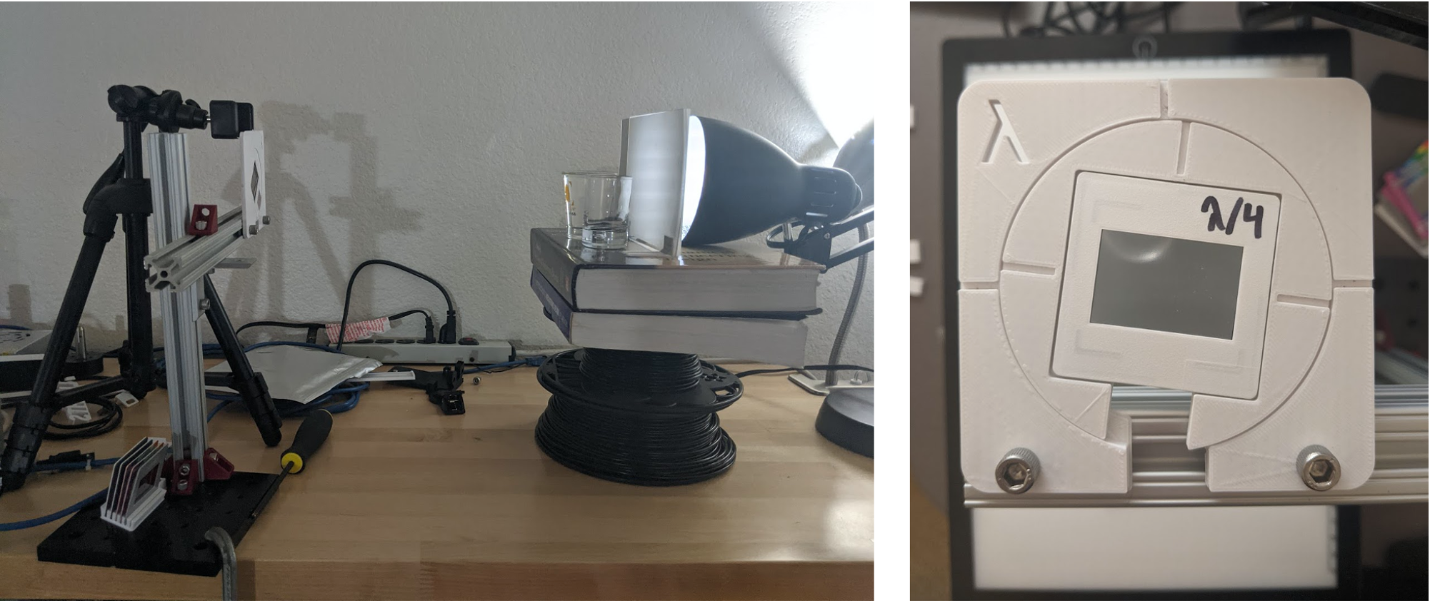
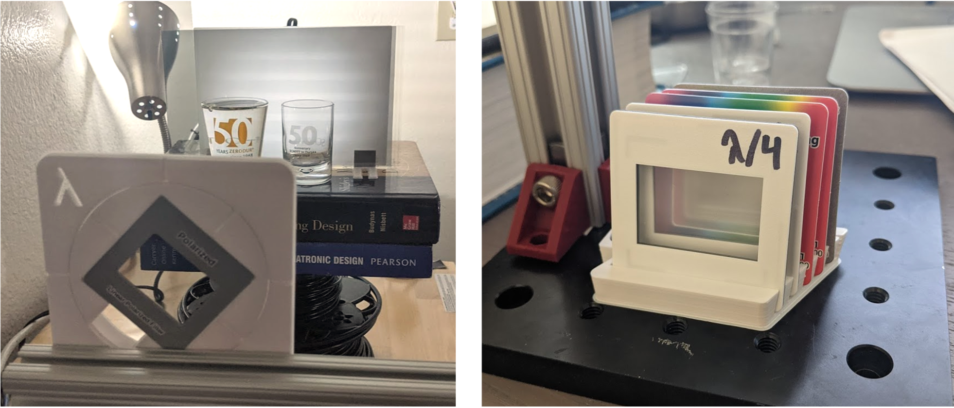
The configuration places a sheet polarizer in front of a highly Lambertian and uniform source (a flashed opal diffuser and a LED light bulb in the vertical configuration, or just LED light box tracer). Then is the transparent sample itself, following by a rotating analzyer disk with a slot for interchangeable filters (polarizer/retarders/a combination), and then my cell phone camera. Parts were designed and 3D printed by myself on a nice weekend afternoon. Printed at 4000 mm/s on an Ultimaker 2+ with Atomic Filament Bright White PLA.
With a prismatic solid (a cylinder, cube, etc), the reduced optical path lengths will be same across the entire prism face and so a single color will manifest through the analyzer. But for a conical volume viewed through the horizontal polariscope configuration, it is much more interesting because different annuli have different amounts of induced rotation. This is what happens:
The slope of the conical geometry allows a linear sweep of path lengths to exist. As the analyzer rotates by the angle \(\theta \), "new" colors enter from the edge of the pupil and walk towards the center. A procession of over 360 degrees is shown, where analyzer cycles occur over 180 degrees. This 'march' of color goes from the shot glass rim to where the base 'begins'. Since the colors begin repeating (see how the color of the base always matches one annular slice), it is known that the linearly-polarized light has rotated at least 180 degrees by the time it exits the solution. The following snapshots aren't equally spaced, but they were definitely the most visually-satisfying cuts.
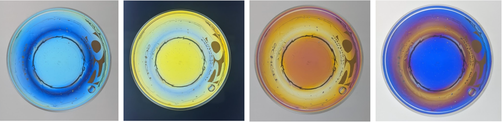
The vertical configuration is also interesting because the thickest optical path is at the very top of the shot glass. I really enjoyed that blue and yellow, and that orange and purple could coexist in the same homogenous liquid volume.
Stress Birefringence and Photoelasticity
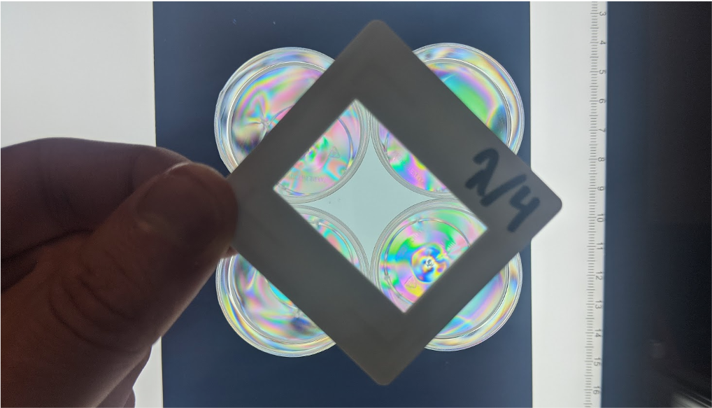
Finally, we are looking at plastic injection molded shot glasses! Birefringence, as introduced earlier, can induce polarization-dependent phase changes. Material birefringence can be introduced into a naturally isotropic material via a manufacturing process that leaves residual stresses. This dimensionally compresses/stretches the lattice of the material and alters the refractive index.
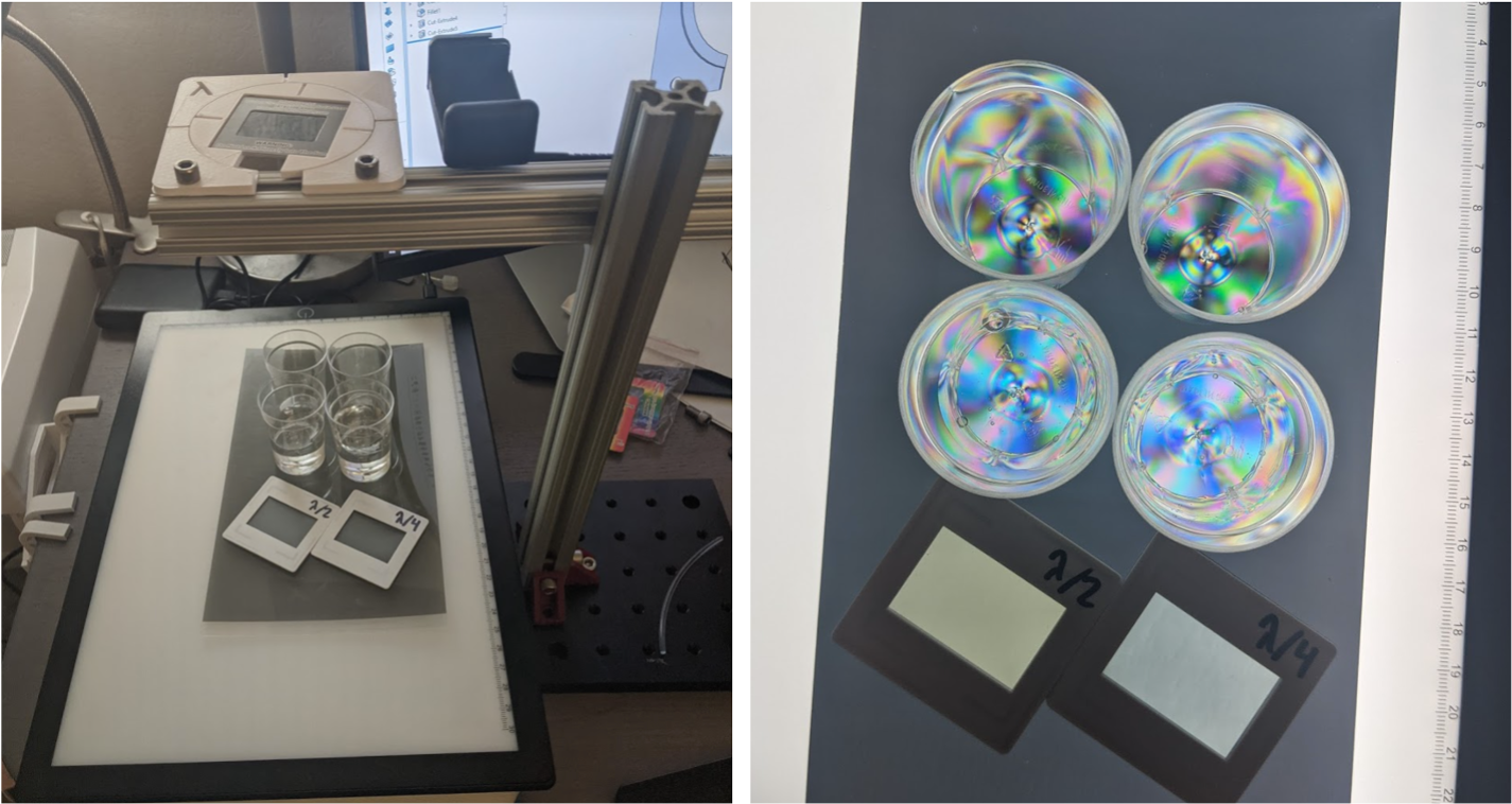
With altered refractive indices between two orthogonal directions of a lattice, a phase is introduced between the decomposed eigenpolarizations that propagate (at different speeds) through the solid. The rays can be thought to 'split' when they propagate through the crystal medium, with one emerging 'faster' than the other. After emerging, the superimposed light is not linearly polarized as it had entered but has gained some ellipticity. This automatically implies that the second crossed polarizer cannot generally extinguish all of the light (it'll still do a good job if the eigenpolarizations of both elements are aligned). Through a crossed polariscope assembly, visual photoelastic effects are especially noticeable at junction and boundaries, where flow stress is high - this is very common in injection molding where thin walls and rapid cooling are the norm.
The amount of retardance induced by propagating through a stressed isotropic material is described by the stress optic law, which relates mechanical principal stresses and stress optic coefficient. \(\Delta\) is the retardance induced by a difference in principal stresses, as formalized by the stress tensor matrix. The coefficient \(C\) is a 6x6 matrix whose elements relate the Young's Modulus, \(E\), Poisson's Ratio, \( \nu\), and the ellipticity of the refractive index ellipsoid.
$$ \Delta = \frac{2 \pi t}{\lambda}C(\sigma_{xx}-\sigma_{yy})$$
$$ \vec{\sigma} = \begin{bmatrix} \sigma_{xx} & \tau_{xy} & \tau_{xz}\\ \tau_{yx} & \sigma_{yy} & \tau_{yz}\\ \tau_{zx} & \tau_{zy} & \sigma_{zz}\\ \end{bmatrix} $$
But why does color appaer when these plastics were originally transparent? Built up by the last section, each color transmitted through the medium experiences a different retardance and phase change. When the split rays of each color recombine, sometimes the induced phase delay allows destructive interference between the two split rays. The colors that do not interfere as strongly through the plastic remain and the combination of those colors is what the plastic appears be. With the Michel-Lévy Color Interference Chart, one can judge the induced retardance and figure out the crystal structures of a mineral rock section.
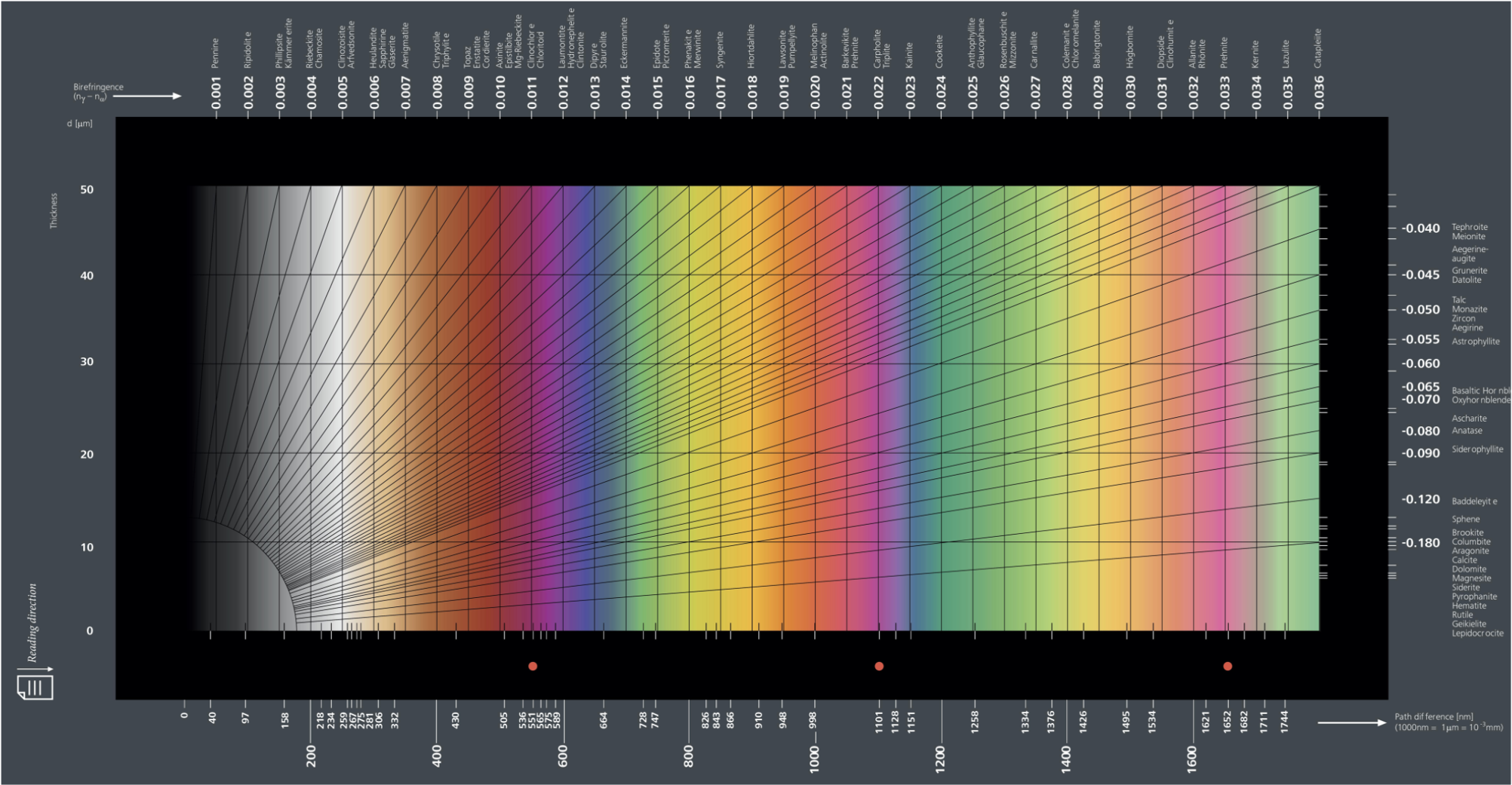
Via Zeiss Microscopy's 'Michel-Lévy Interference colour chart'. CC BY-SA 2.0. The absolute best resource I found about its application and usage is by an expert named John Delly on this page.
Conclusions
Anyway, I hope you enjoyed looking at light leakage phenomena of shot glasses. All of these vivid effects are directly related to polarization and demonstrate its significance in media we usually percieve as perfectly clear and homogenous.