
Henry Quach
Optical EngineerPrecision Rotary Stage Restoration
Introduction
I found a godly Klinger rotary stage in lab - godly if only the coupler connecting the stepper input shaft and rotary transmission mechanism wasn't broken. The stage is extraordinarily nice because it has a high gearing ratio, which affords smaller rotary step increments. For example, a 180 degree rotation of the input shaft yields a 1 degree angular displacement of the main stage. Even without microstepping, a typical 1.8 degree movement resolution & accuracy of the stepper would yield reliable 0.01 degree steps. With sufficent torque provided by the power supply, 2000 step microstepping helps us approach 0.001 degree movement accuracy without empty resolution. Easily this stage was worth fixing.
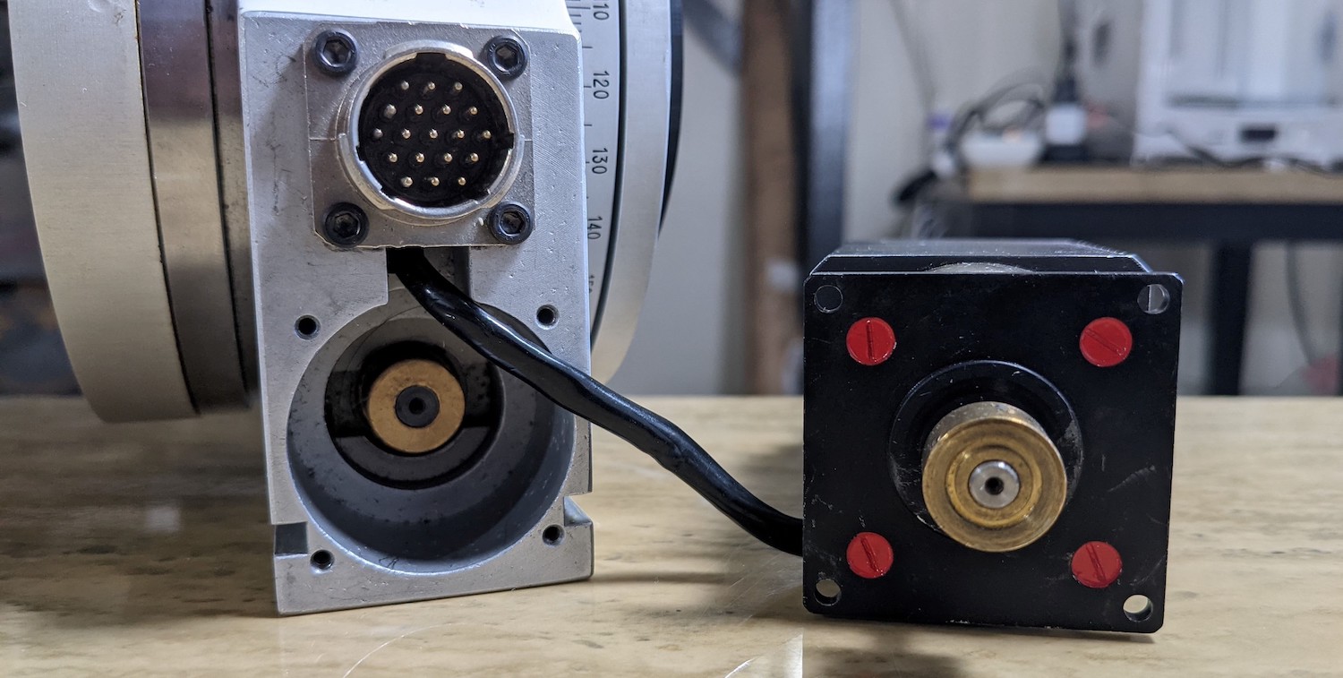
Figure 1. The two halves of this assembly are attached by a faceplate with M2.5 and M3 bolts. Brass shaft collars are seated onto 5 mm and 7 mm diameter power transmission shafts, each seated by one or two M3 set screws. The problem is that the original coupler holding these two was missing and replaced at some point by a one-off helical coupling.
Missing Coupling Modeling and Design Plan
Some sleuthing about the broken assembly revealed that the shaft collars have set-screw holes that are NOT symmetrical about the collar's midplane. My initial aversion to fixing the stage was wholy motivated by how difficult tightening the set screws would be. At that time, I thought I would need to insert short arm of an allen key into the tight machined bore and make painful incremental rotations within the oppressively limited working space.
It turns out that the brass collars were inserted UPSIDE DOWN. Inverting them, I learned that there was an external access hole that lined up perfectly with the position of the brass collar set screw hole. The probable reason why the collar was inverted was because the set screw was replaced at some point. In an optics lab, M3x6mm long set screws are common because these are the stock ones included with a Thorlabs metric hardware set. Yet the length 6 mm is problematic - the annulus of the brass collar is ~5.5 mm, so using the 6 mm set screw to constrain the collar against the transmission shaft produces interferences. Naturally, the person who modified the collar solved this problem by inverting it, but lost the ability to use the external access hole.
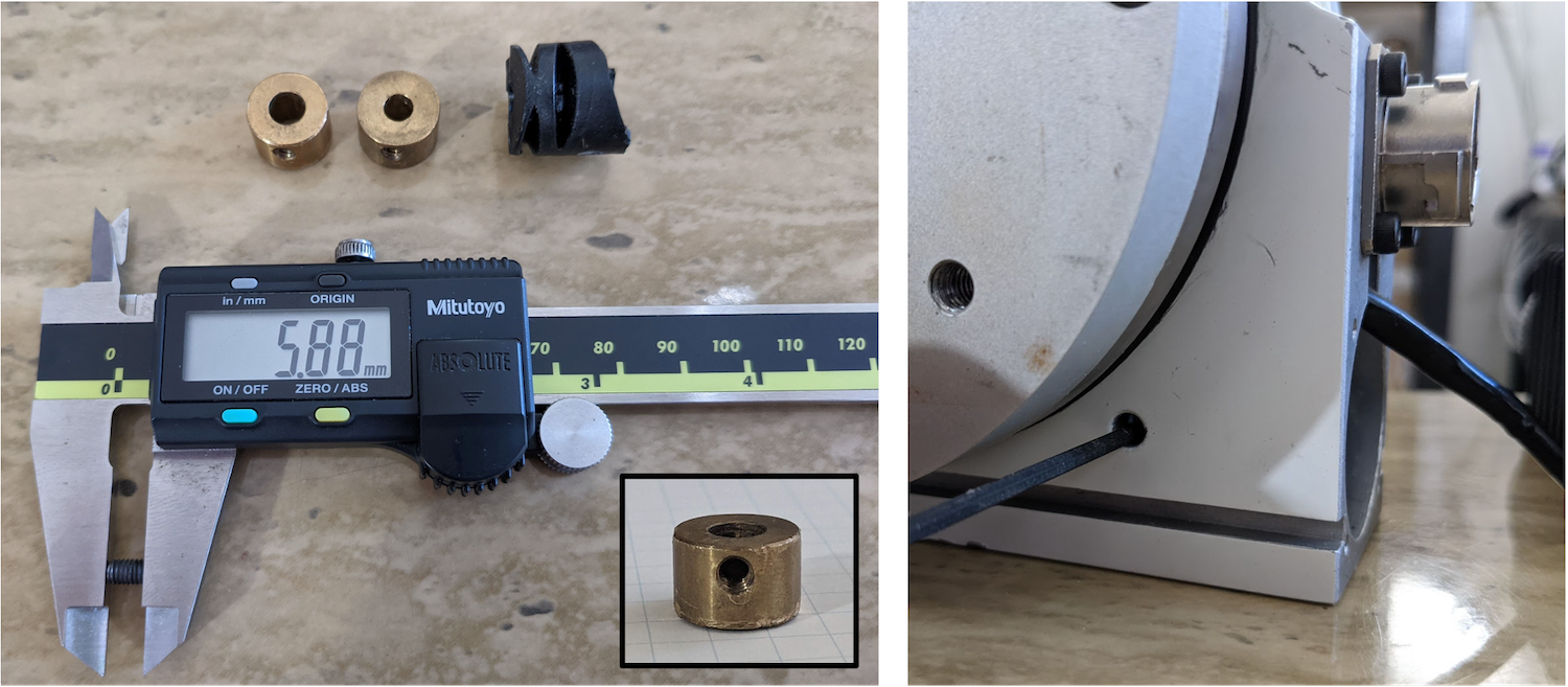
Figure 2. Measuring the M3 set screw length showed that it exceeded the thickness of the annular collar by just ~0.5 mm, which produces significant interference and limits the rotation of the coupled collar-shaft assembly to just ~30 degrees.
Coupler Prototyping and Modeling
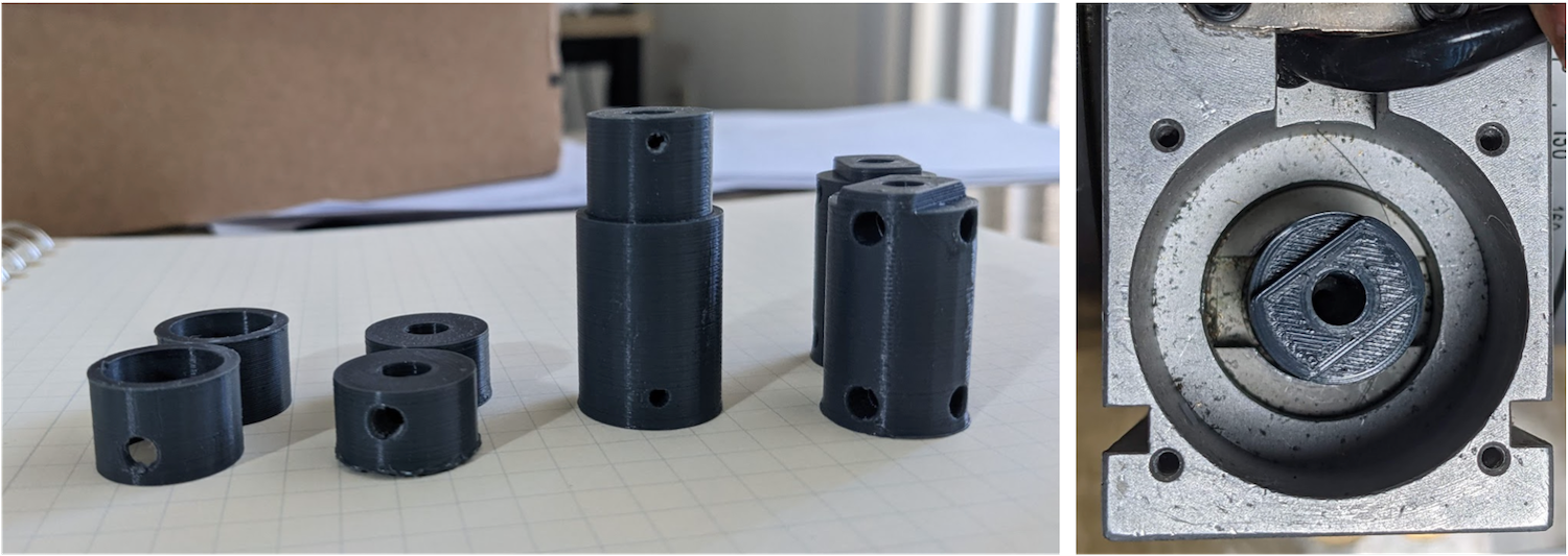
Figure 3. The prototype began by printing the 7 mm bore until the printed hole perfectly matched the dimensions of the steel shaft. Then I worked up to the opposite power transmission shaft. Eventually, it looked great and felt great and a final was ready to go!
I found the critical dimensions of the each power transmission shafts, the maximum diameters of the bores, and stepwise vertical ordinates for the set screws along the longitudinal axis of the proposed coupler. As seen in Figure 2, a helical coupler was originally 3D printed. This geometrical coupler paradigm obtains pretty good torsional stiffness in metal parts for its weight (and is a lot kinder to misalignment) but this geometry is detrimental for plastic 3D printed parts. Maximum shear strength of an ABS/PLA coupler will be the limiting factor rather than shear modulus, so I chose to make as solid of a coupling as I could get (max diameter, max infill). Misalignment is basically not allowed because I make the coupler so solid. As a last element of design, I decided to use two orthogonal set screws to obtain maximum torque transfer and postpone the eventuality of slip. I bought M3x5 SST cup-point set screws for this, thought i would have preferred a softer material to not permanently mar the shafts.
Final Dimensions, Drawing, and Re-Assembly
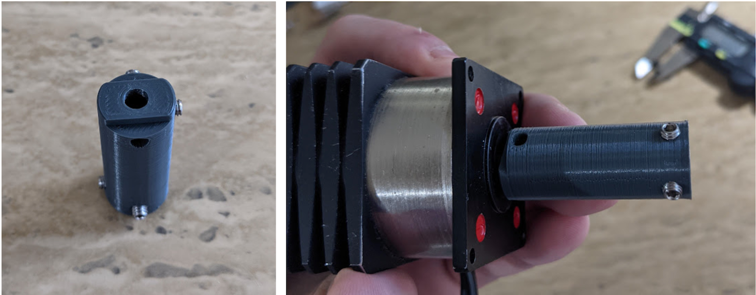
Figure 4. Final shaft coupler with opposite orthogonal pairs of set screws to reduce slippage. The assembly process began with fastening the set screws to the stepper shaft and ended with tightening the set screws at the bottom thorough the machined access bore of the stage. Thank you DFM designers at Klinger Scientific.
My drawing showing the cross section views is below. I designed a flat into the top of the coupler because the feature was handy when I needed constrain the coupler from rotation with my Leatherman.
A final look at the beautiful stage! It works perfectly with the precision dial turning the stage 2 degrees per full 360 degree stepper shaft rotation.
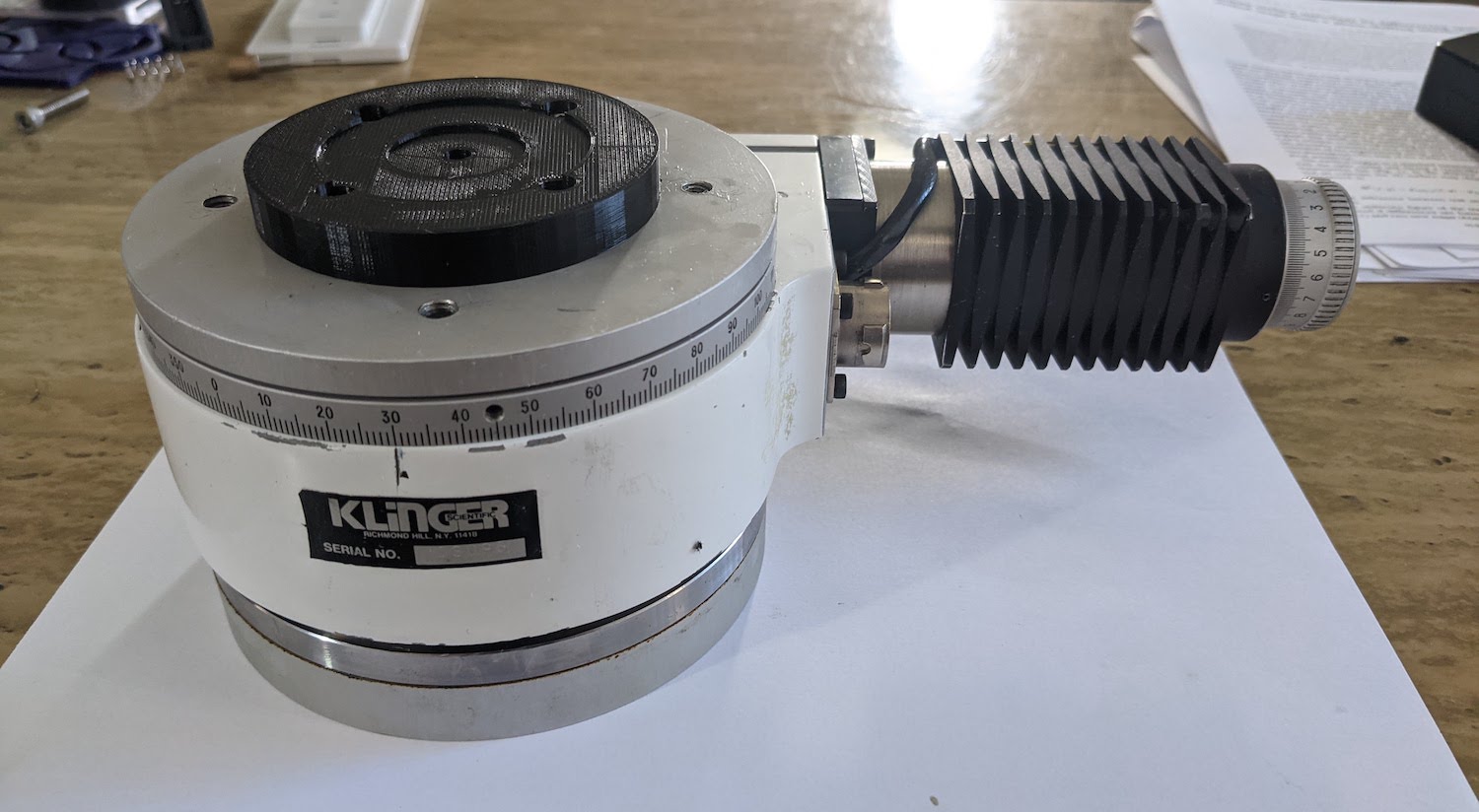
Figure 5. Ready for use as reliable hardware in a publication!
Motor Control in Matlabb>
I implemented motor control through a Matlab interface. The diagram is laid out below where I use a typical National Instruments DAQ to send step and direction signals to a stepper driver. The driver simply converts these to correct bipolar signals to the stage stepper. This is powered by a fairly low voltage power supply. The code I use to instantiate the stepping environment and connect to the ni-DAQ is given below, as well as the primary rotation signal function, outputSingleScan(s,A).
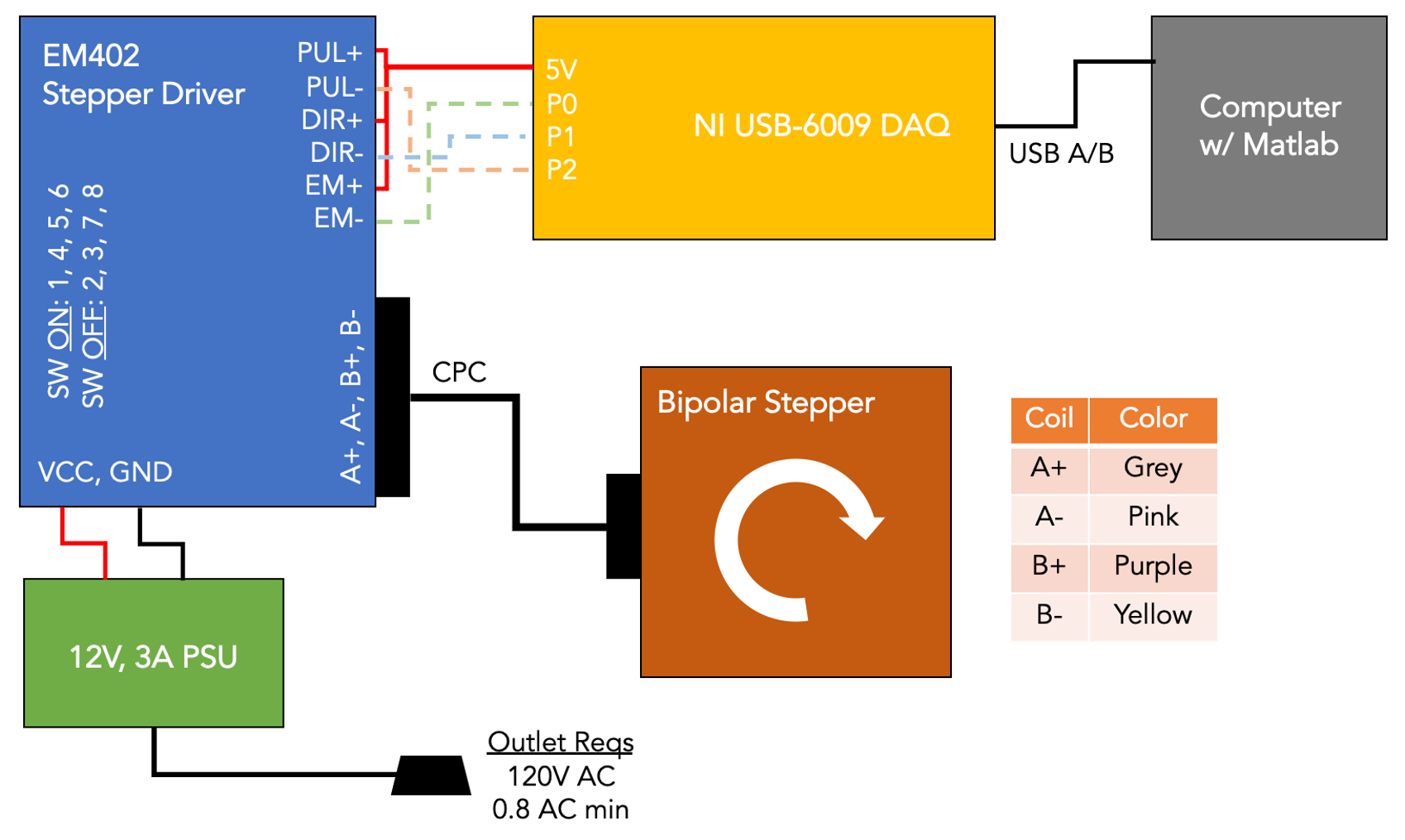
Figure 6. Control scheme with hardware connections.
                                        %% Motor Configuration
                                        % Based from Heejoo's B_SCOTs_rotation_module2
                                        % Full revolution takes 216 seconds

                                        %% 1.1 Check if NI USB-6009 DAQ is connected
                                        % devices = daq.getDevices

                                        s = daq.createSession('ni'); % create daq session 's'
                                        % assigns channel, assign instrument name, Ports 0-2, I/O type
                                        addDigitalChannel(s,'Dev1','Port0/Line0:2','OutputOnly');

                                        %% 1.2 Turn on stepper motor
                                        % Note: A = [A1 A2 A3]
                                        % where A1 = 1 sets pulse signal to rising edge
                                        %       A1 = 0 sets pulse signal to falling edge
                                        % where A2 = 1 sets rotation direction counterclockwise
                                        %       A2 = 0 sets rotation direction clockwise
                                        % where A3 = 1 enables motor driver power

                                        A = [1 1 0];

                                        %% 2.0 Set Rotation Angle (degrees)
                                        RotationAngle = 360

                                        %% 2.1 Execution of Rotation

                                        for N = 1:round(RotationAngle/0.01);
                                            A = [1 1 1]; % pulse to rising edge
                                            outputSingleScan(s,A);
                                            A = [0 1 1]; % pulse to falling edge
                                            outputSingleScan(s,A);
                                        end
Testing Rotation Accuracy
I chose to test rotation step accuracy with a quadrature rotary encoder. I chose the capacitive 4096 PPR encoder from CUI, which has a limited resolution of 0.02 degrees. The limiting factor in incremental encoders is reading the pulses while not the number of pulses. Higher PPR (#pulses per revolution) means a faster count frequency for a fixed angular speed. The only choice for high PPR encoders is to use a buffer, which counts and dumps the number into an external capture device very reliably. I got one by Super Droid Robots for a TI buffer and it worked fabulously. Code for counting is below.
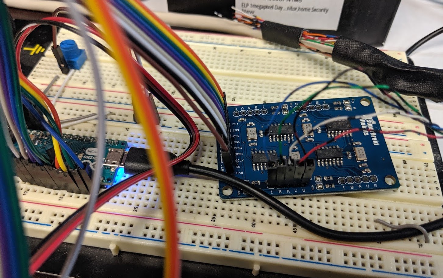
Figure 7. The messy, but working breadboard layout.
                                    /*
                                       Dual LS7366 Quadrature Counter Test Code
                                       AUTHOR: Jason Traud
                                       DATE: June 22, 2013

                                       This is a simple test program to read encoder counts
                                       collected by the LS7366 breakout board. The counts are
                                       then displayed in the Arduino's serial monitor at a
                                       baud rate of 9600

                                       Hardware: Arduino Uno R3
                                       Powered

                                       LS7366 Breakout    -------------   Arduino
                                       -----------------                    -------
                                                MOSI   -------------------   SDO (D11)
                                                MISO   -------------------   SDI (D12)
                                                SCK    -------------------   SCK (D13)
                                                SS1    -------------------   SS1 (D7)
                                                SS2    -------------------   SS2 (D8)
                                                GND    -------------------   GND
                                                VDD    -------------------   VCC (5.0V)

                                       License: CCAv3.0 Attribution-ShareAlike (http://creativecommons.org/licenses/by-sa/3.0/)
                                    */
                                    void setup() {
                                     Serial.begin(9600);      // Serial com for data output
                                     lcd.begin(20,4); // Initializes the interface to the LCD screen, and specifies the dimensions (width and height) of the display }
                                     initEncoders();       Serial.println("Encoders Initialized...");
                                     clearEncoderCount();  Serial.println("Encoders Cleared...");
                                    }

                                    void loop() {
                                    delay(250);

                                     // Retrieve current encoder counters
                                    encoder1count = readEncoder(1);
                                    encoder2count = readEncoder(2);
                                    //float mvmt = encoder2count*.775146; //(360/(4096*4)*12700/360
                                    //Serial.print(" Encoder 2 Travel Distance: "); Serial.print(mvmt); Serial.println(" um");
                                    //lcd.clear();
                                    lcd.setCursor(0,0);
                                    lcd.print("Stepper (Deg)");
                                    lcd.setCursor(0,1);
                                    lcd.print(float(encoder1count)*360/(4096*4));
                                    lcd.setCursor(0,2);
                                    lcd.print("Timing Belt (Deg)");
                                    lcd.setCursor(0,3);
                                    lcd.print(float(encoder2count)*360/(4096*4));

                                    void setup() {
                                     Serial.begin(9600);      // Serial com for data output
                                     lcd.begin(20,4); // Initializes the interface to the LCD screen, and specifies the dimensions (width and height) of the display }
                                     initEncoders();       Serial.println("Encoders Initialized...");
                                     clearEncoderCount();  Serial.println("Encoders Cleared...");
                                    }
The only annoying part of this was soldering the pins and connector cables. I soldered and crimped Dupont connectors onto the 22 AWG wires for easier and more reliable use.
Tying together an Arduino Nano, the Quad LS7366R buffer chip, and a 20x4 LCD screen was messy at first, but I did clean it up. Here's the beautiful mounting scheme I came up with that printed in just about an hour and a half. It uses M3 screws to secure all the electronics and has mounting holes for common #1/4-20 holes in optical tables.
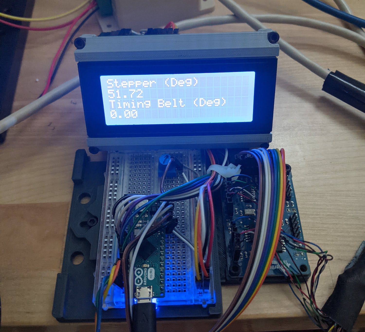
Figure 8. The cleaned-up and compact layout.
Runout Testing
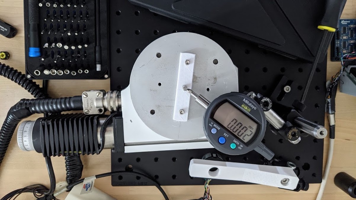
Figure 9. Encoders have some natural resistance to shaft decenter, but why add inaccuracy to your measurements? To find the center, I printed out a slotted piece that I adjusted linearly until the dial gage measured minimal RMS runout over a full rotation.
Rotation Accuracy
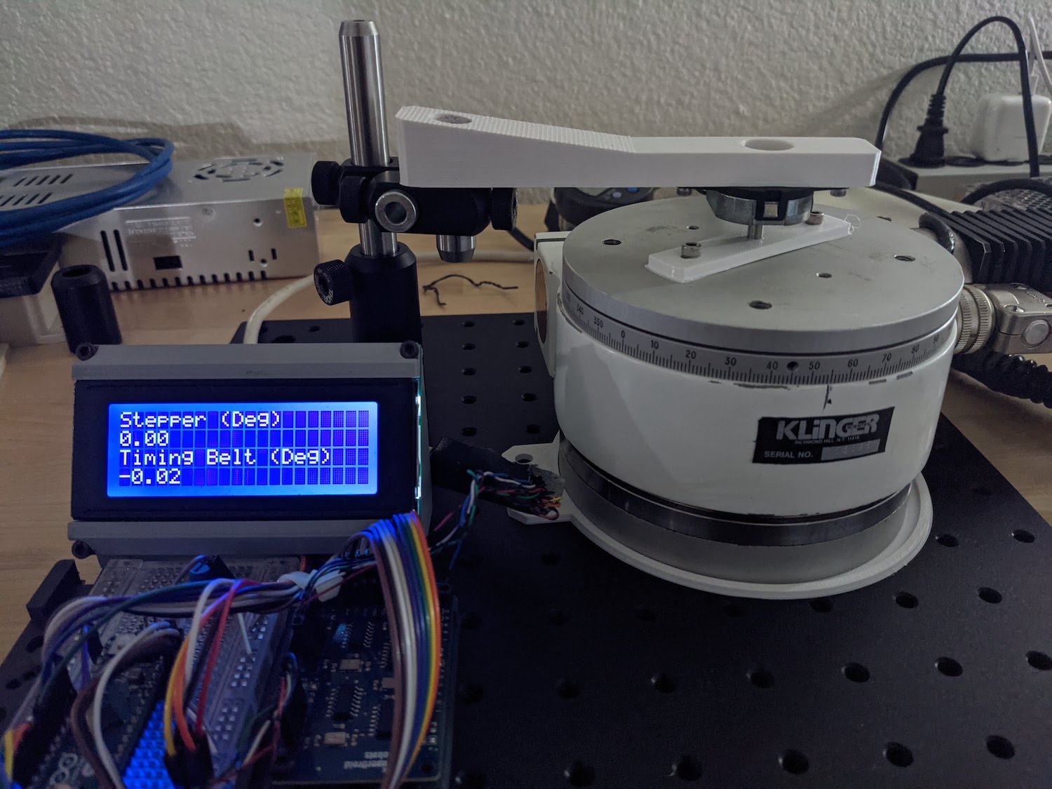
Figure 10. In the end, my requirement for 0.2 degrees for a project I'm working on worked very handily. I should plot the measured angular displacements on the graph for more completeness though.
Conclusions
This was a fun Saturday afternoon project. The stage is restored and fully operational!